
Content Writer & SEO Specialist
Content Writer & SEO Specialist
Aditya Sharma is a content writer at OptM Solutions specializing in automotive electronics, embedded systems, telematics, electric vehicle technologies, connected mobility, and autonomous driving technologies.
LinkedIn ProfileFor decades, the automotive industry treated vehicle connectivity as an aftermarket fleet-tracking accessory. Today, in the era of Software-Defined Vehicles (SDVs), the internal mechanisms of a Telematics Control Unit (TCU) dictate the core capabilities of modern transportation ecosystems. From an OEM integration perspective, understanding What is Telematics Control Unit is no longer enough; engineering teams must understand exactly how these systems capture, compute, and transmit data under extreme operational stress.
How Does a Telematics Control Unit Work?
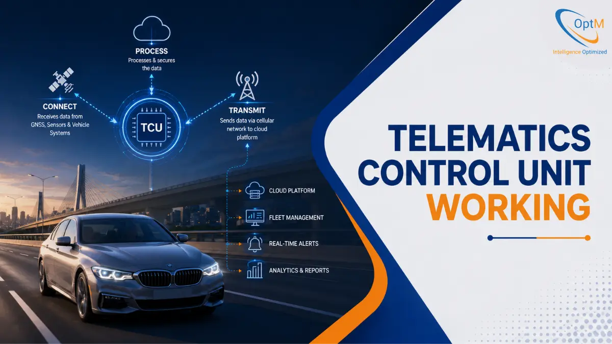
A Telematics Control Unit works by physically intercepting high-frequency signals from internal vehicle networks, validating the payload data using local edge algorithms, and broadcasting it securely over cellular networks. It acts as a bidirectional translation node, transforming raw automotive bus packets into secure cloud messages and vice versa.
The mandate for high-performance TCUs is driven by sheer data volume. According to a comprehensive analysis by McKinsey & Company, modern connected cars feature roughly 100 million lines of programming code and process up to 25 gigabytes of data every single hour. Pushing this immense raw data load directly to the cloud is financially and technically impossible. The TCU must therefore act as an intelligent gateway, filtering the noise and transmitting only the critical anomalies.
This guide breaks down the macro narrative of vehicle telemetry—tracking the journey of a data packet from a millisecond-level physical voltage change on a copper wire to an actionable, cloud-native datapoint.
Technical Foundation: The Pre-Requisites of TCU Data Ingestion
Before any data can be uploaded to a fleet management dashboard, the TCU must physically link to the vehicle’s nervous system. The Telematics Control Unit Architecture relies on highly specific in-vehicle network interfaces that govern how the unit speaks to individual Electronic Control Units (ECUs).
The In-Vehicle Network Interfaces
In production-grade automotive environments, the TCU does not generate diagnostic data; it harvests it. It achieves this by tapping into three primary network backbones:
- Controller Area Network (CAN Bus & CAN-FD): The standard CAN bus operates on differential voltage signaling across two wires (CAN High and CAN Low). When an ECU needs to broadcast engine RPM, it changes the voltage on these lines. The TCU reads these voltage shifts as binary code. Traditional CAN operates at speeds up to 1 Mbps using 11-bit identifiers. However, modern Components of Telematics Control Unit increasingly support CAN-FD (Flexible Data-rate), which pushes bandwidth up to 8 Mbps, allowing larger payloads necessary for complex sensor data.
- SAE J1939 Protocol Standard: Used heavily in commercial trucks, agriculture, and heavy machinery, J1939 operates on top of the CAN physical layer but uses extended 29-bit identifiers. Our engineers map Parameter Group Numbers (PGNs) and Suspect Parameter Numbers (SPNs) to extract exact metrics like diesel exhaust fluid levels or transmission oil temperatures.
- Automotive Ethernet (100Base-T1 / 1000Base-T1): As vehicles integrate LiDAR, radar, and multiple interior cameras, traditional CAN buses choke on the data volume. Automotive Ethernet provides high-speed, multi-gigabit backbones. TCUs equipped with Ethernet switches manage the heavy lifting required for Advanced Driver Assistance Systems (ADAS) and raw video streaming.
The Physical Connection Nodes
At the hardware board level, the connection is managed by transceivers. These microchips convert the physical voltages from the vehicle bus into logic-level signals (RX/TX) that the TCU’s main processor can understand. Because vehicles are electrically noisy environments, these lines are heavily fortified with common-mode chokes to filter electromagnetic interference (EMI) and transient voltage suppression (TVS) diodes to block electrostatic discharge (ESD) spikes.
The 6-Stage Lifecycle of Telematics Processing
To truly understand Telematics Control Unit Working, we must analyze the step-by-step lifecycle of a data packet. This six-stage pipeline dictates how an OptM automotive-grade gateway converts analog vehicle physics into digital cloud intelligence.
Step 1: Physical Data Ingestion & Signal Interception
The workflow begins at the exact millisecond an event occurs—for example, a driver applies the brakes abruptly. The ABS ECU broadcasts a message across the CAN bus.
The Micro-Mechanics:
The TCU’s vehicle interface controller samples the CAN lines continuously. However, if a vehicle undergoes a sudden emergency braking event, hundreds of sub-systems (powertrain, seatbelts, airbags) flood the network simultaneously. This is known as a "bus load spike."
If the TCU's central processing unit (CPU) had to manually read every single message during a spike, it would freeze. To prevent data loss, industrial-grade TCUs utilize Direct Memory Access (DMA). The CAN controller hardware writes the incoming messages directly into the local RAM chips, bypassing the core CPU entirely. The CPU is only interrupted once a predefined buffer is full, allowing it to process massive bursts of data without dropping critical safety frames.
Step 2: Protocol Translation & Hardware Abstraction
Once the raw data is safely inside the TCU's memory, it looks like an unintelligible hex array (e.g., 0x0CF00400). It must be translated.
The Raw-to-Digital Conversion:
The internal software stack contains a parsing engine loaded with a Database (DBC) file. This file acts as a decoder ring. It tells the processor that the first 8 bits of 0x0CF00400 represent engine RPM, and the next 8 bits represent throttle position. The software applies a mathematical scaling factor, converting the raw hex into physical values: Engine RPM = 2100, Throttle Position = 84%.
The Hardware Abstraction Layer (HAL):
In OptM’s embedded architecture, this translation process sits above a Hardware Abstraction Layer (HAL). The HAL is critical because it decouples the underlying physical chips from the application software. If a Tier 1 supplier decides to switch from an NXP microprocessor to an STMicroelectronics chip due to supply chain shortages, the core translation software does not need to be rewritten. The HAL handles the hardware-specific translation natively.
Step 3: Edge Computing, Parsing, & Frugal Filtering
Streaming 100% of the translated vehicle traffic over a cellular network is a guaranteed way to exhaust cellular data budgets and overwhelm cloud databases. This is where edge computing becomes the TCU's most valuable asset.
Threshold-Based & Deterministic Filtering: Rather than sending every data point, the processor applies frugal filtering algorithms at the edge.
- Dead-Band Filtering: The TCU only records a metric if it changes by a statistically significant margin. For instance, the system will ignore coolant temperature messages unless the value fluctuates by more than 1°C.
- Time-Interval Ingestion: Standard operational data (like GPS location and fuel level) is packaged quietly in the background at regular, low-frequency intervals (e.g., once per minute).
- Event-Driven Interrupts: If an active Diagnostic Trouble Code (DTC) triggers, or an airbag deployment is detected, the TCU bypasses all time-interval filters. It immediately packages a high-priority payload and forces an emergency upload to the cloud.
This edge-driven Telematics Control Unit Functions approach reduces cellular payload sizes by up to 80% while ensuring critical safety data is transmitted with zero latency.
Step 4: Spatial-Temporal Synchronization (GNSS + Dead Reckoning)
A data point is useless if fleet managers do not know exactly where and when it occurred. The TCU must append precise 4D coordinates (Latitude, Longitude, Altitude, and Timestamp) to every payload.
Satellite Acquisition Mechanics: Modern TCUs feature multi-constellation Global Navigation Satellite System (GNSS) receivers. Instead of relying solely on standard GPS, they simultaneously lock onto GLONASS (Russia), Galileo (Europe), and BeiDou (China) satellites. This ensures a rapid "Time to First Fix" (TTFF) even in dense urban canyons.
Dead Reckoning Algorithms: What happens when a commercial truck drives into a three-mile subterranean tunnel, completely losing satellite visibility? Standard GPS trackers freeze or show the vehicle flying across the map. An automotive-grade TCU utilizes Dead Reckoning. It fuses the last known GNSS coordinate with data from an internal 3-axis accelerometer and gyroscope (IMU). By cross-referencing this physical inertia with the vehicle’s wheel speed pulses (pulled from the CAN bus), the TCU mathematically calculates the vehicle's exact position inside the tunnel, ensuring seamless tracking mapping.
Step 5: Data Serialization, Encapsulation, & Cryptographic Security
Once the payload is translated, filtered, and geo-tagged, it must be prepared for the hostile environment of the public internet.
Data Packaging Frameworks:
Legacy systems packaged data in heavy text formats like JSON or XML. In modern TCU Integration with CAN Bus, GPS, LTE/5G and Cloud Platforms, engineering teams utilize lightweight binary serialization formats like Google Protocol Buffers (Protobuf) or MessagePack. Protobuf strips out all unnecessary text characters, compressing the payload into a microscopic binary string, which minimizes airtime and reduces power consumption.
The Cryptographic Handshake:
Before transmission, the data must be secured against interception—a core focus when addressing Cybersecurity Challenges in Telematics Control Unit Development
- Hardware Security Module (HSM): The binary payload is passed to a physically isolated chip on the board called the HSM.
- Encryption: The HSM encrypts the payload using localized asymmetric keys (like RSA or ECC).
- TLS Wrapping: The encrypted data is wrapped in Transport Layer Security (TLS 1.3) protocols.
- Digital Signatures: Finally, the HSM attaches a digital signature. When the cloud server receives the packet, it verifies this signature to ensure the data was not spoofed by a malicious actor mimicking the vehicle.
Step 6: RF Modulation, Network Selection, & Uplink Transmission
The final stage is broadcasting the secure binary payload to the cell tower.
Multi-Band Network Navigation:
The internal cellular modem converts the digital bitstream into high-frequency analog radio frequencies (RF). Modern mobility solutions require highly adaptable modems. The system will prioritize 5G Standalone (SA) networks for Ultra-Reliable Low-Latency Communication (URLLC), which is necessary for V2X (Vehicle-to-Everything) hazard warnings. However, if the vehicle enters a rural area, the modem automatically executes a fallback sequence, shifting to 4G LTE, or even Cat-M1/NB-IoT networks, based on signal strength metrics.
Queue Management in Dead Zones:
If a vehicle is driving through a remote logging route with absolutely zero cellular coverage, the TCU does not discard the data. It utilizes non-volatile flash storage (eMMC or SPI Flash) to buffer the encrypted payloads. The internal queue management system tracks these files chronologically. The exact moment the vehicle regains a cellular handshake, the TCU executes a bulk burst-upload, clearing its local memory backlog and ensuring fleet operators experience zero data gaps.
Hardware-Software Orchestration: Internal Component Interactions
While the six-stage data lifecycle handles telemetry, the TCU must also sustain its own operational health. The internal hardware and software must constantly negotiate power states and system stability.
The Power Management Dynamic
Automotive batteries have strict parasitic draw limits. If a vehicle is parked at an airport for three weeks, the TCU cannot drain the 12V battery, leaving the driver stranded.
The Power Management IC (PMIC) is the gatekeeper of the TCU’s energy consumption. When the vehicle ignition is turned off (indicated by a drop in the KL15 ignition wire), the PMIC forces the main CPU and cellular modem into a deep sleep mode, reducing power draw from several watts down to a few milliamps. However, it keeps a tiny, ultra-low-power micro-controller awake. If this micro-controller detects a sudden vibration (via the accelerometer) or receives a specific SMS "wake-up" ping from the cloud, it triggers the PMIC to boot the entire system back up in seconds.
The Watchdog Timer Architecture
Software anomalies happen. A memory leak or an unhandled exception could theoretically freeze the TCU’s operating system. In consumer electronics, a user simply unplugs the device to reboot it. In an automotive environment, manual reboots are impossible.
To guarantee 100% uptime, TCUs deploy an independent, hardware-isolated clock system called a Watchdog Timer. The main software must send a periodic "kick" signal to the Watchdog Timer every few milliseconds. If the software freezes and misses a kick, the Watchdog Timer physically cuts the power to the CPU and forces a hard reset, restoring the system to a healthy state without human intervention.
Performance Latency Matrix
| Processing Stage | Typical Execution Latency | Primary Hardware Driver |
|---|---|---|
| CAN Bus Ingestion | 1 – 5 milliseconds | CAN/J1939 Transceiver & DMA Controller |
| Protocol Translation | 5 – 10 milliseconds | Application Processor (Embedded Linux / RTOS) |
| Edge Anomaly Filtering | 2 – 8 milliseconds | Core MCU Logic Algorithms |
| HSM Encryption | 10 – 25 milliseconds | Dedicated Hardware Security Module |
| Cellular Uplink (5G) | 10 – 20 milliseconds | Baseband Processor & RF Antenna |
| Total Edge-to-Cloud | ~28 – 68 milliseconds | End-to-End System Optimization |
Note: Latency varies based on exact payload size and geographic cellular tower proximity.
Bidirectional Operations: Over-The-Air (OTA) and Remote Commanded Execution
Data does not flow in just one direction. To justify the substantial investment in connected mobility and reap the full Telematics Control Unit Benefits, the system must execute incoming commands.
According to market forecasts by Grand View Research, the global automotive telematics market is projected to reach USD 170.43 billion by 2030, growing at a CAGR of 16.6%. This explosive financial growth is driven primarily by the TCU's ability to act as a bidirectional node for software monetization and remote repairs.
Secure Remote Diagnostics Execution
The Downlink Pipeline allows fleet managers to push commands to the vehicle rather than simply monitoring it. Using protocols like Unified Diagnostic Services (UDS over IP / ISO 14229), a fleet operator can send a command from a cloud dashboard to the TCU. The TCU authenticates the command and translates it into a physical action on the bus—such as forcing a diesel particulate filter (DPF) regeneration cycle on a commercial truck, locking the doors, or throttling the engine speed for a geofenced zone.
OTA Flashing Coordination
The most complex bidirectional function is the Role of TCU in OTA Updates and Remote Vehicle Diagnostics. When an OEM releases a software patch for an infotainment system or a powertrain ECU, the TCU acts as the secure local download engine.
- It connects to the OEM's cloud repository and downloads the delta-firmware package (only the code that has changed, saving bandwidth).
- It verifies the cryptographic signature of the file to ensure it is not a malicious payload.
- It waits for the vehicle to enter a safe state (e.g., parked, engine off, parking brake engaged).
- It assumes the role of a diagnostic master node, using the CAN bus to systematically flash the updated code into the target ECU, completely eliminating the need for the vehicle to visit a physical dealership.
Engineering Realities & Deployment Bottlenecks
Developing an architecture that looks good on a schematic is vastly different from deploying hardware into the hostile environment of a vehicle chassis. Understanding the Challenges in Telematics Control Unit Development is what separates consumer IoT devices from industrial automotive gateways.
Electrical Transient Protection
Automotive power supplies are notoriously unstable. When a vehicle's starter motor engages, the battery voltage can drop drastically (cold cranking). Conversely, if the battery is suddenly disconnected while the alternator is running, a massive voltage spike called a "load dump" floods the electrical system. The TCU's internal circuitry must be heavily regulated by isolated DC-DC converters to survive these ISO 7637-2 transients without frying the sensitive 5G modems or microprocessors.
Thermal Dissipation on Sealed Units
Processing 5G data uploads while executing heavy edge-computing algorithms generates significant heat. However, because TCUs are often mounted in harsh environments (under the dashboard or inside commercial truck chassis), they must be sealed against dust and moisture (IP65 / IP67 ratings). Because engineers cannot use internal cooling fans, the heat must be managed through passive thermal conduction. The PCB is designed to draw heat away from the processor and modem, transferring it to custom thermal pads connected to a die-cast aluminum housing, allowing the enclosure itself to act as a heatsink.
Network Jitter and Latency Mitigation
Vehicles move. A passenger car traveling at 120 km/h will rapidly pass between different cellular tower zones. As the modem negotiates handovers from one cell tower to the next, network jitter and temporary packet loss are inevitable. The embedded software must utilize robust Transmission Control Protocol (TCP) handshakes and localized MQTT Quality of Service (QoS) levels to guarantee that no diagnostic payloads are dropped or duplicated during high-speed tower transitions.
The OptM Engineering Architecture
Navigating the complexities of high-frequency data ingestion, hardware abstraction, cryptographic security, and cellular modulation requires more than just integrating off-the-shelf components. It demands a holistic, production-ready system architecture.
At OptM Solutions, our embedded systems engineering teams develop industrial-grade automotive platforms built specifically for these hostile data environments. By leveraging highly optimized Embedded Linux baselines, we ensure real-time data processing with zero frame drops. Our software frameworks feature built-in edge logic that filters noise at the hardware level, combined with secure CAN/J1939 bridging systems that guarantee frictionless integration for both commercial fleets and electric vehicle (EV) ecosystems.
From navigating the Role of TCU in Connected Vehicle Ecosystems to supporting advanced smart city V2X infrastructure, the OptM gateway serves as the definitive bridge between raw vehicle physics and scalable enterprise cloud intelligence.
Conclusion & Strategic Call to Action
The Telematics Control Unit is no longer a passive observer; it is the active central nervous system of the connected vehicle. As we have explored in this deep dive into its working lifecycle, a TCU must seamlessly ingest raw electrical signals, translate complex protocols, compute actionable intelligence at the edge, and broadcast secure payloads over dynamic cellular networks—all within milliseconds.
Understanding this intricate orchestration is critical for OEMs, Tier 1 suppliers, and fleet operators looking to deploy robust software-defined architectures. A failure at any stage of this six-step pipeline results in delayed diagnostics, broken OTA updates, and compromised vehicle security.
For engineering leaders and product teams developing the next generation of intelligent mobility, deploying a scalable, fail-safe communication gateway is non-negotiable. Explore how our production-ready hardware, embedded Linux processing, and secure communication frameworks can accelerate your connected vehicle roadmap by reviewing the full technical specifications of OptM Telematics Control Unit.
Frequently Asked Questions
How fast does the TCU process CAN bus data during a crash?
Using Direct Memory Access (DMA), a TCU can ingest high-speed CAN-FD frames in 1 to 5 milliseconds. DMA allows the incoming data to bypass the main CPU, preventing the system from freezing during massive data bursts.
Why doesn't the TCU send all raw vehicle data directly to the cloud?
Transmitting 100% of raw data would overwhelm cellular networks and incur massive data costs. Instead, the TCU uses edge-computing algorithms to filter out normal behavior, transmitting only critical anomalies or summarized time-interval metrics.
How does the TCU track a vehicle inside a long underground tunnel?
It uses a mathematical process called "Dead Reckoning." By fusing the last known GPS coordinate with live data from its internal 3-axis accelerometer, gyroscope, and wheel-speed pulses, the TCU calculates the exact location locally until satellite signals return.
Why do modern TCUs use Protocol Buffers instead of JSON for data?
JSON is a heavy, text-based format. Protocol Buffers (Protobuf) strip away the text characters, compressing the payload into microscopic binary strings. This reduces cellular payload sizes by up to 80% and drastically accelerates cloud processing.
How does the TCU execute two completely different tasks at once without lagging?
High-end TCUs use an Asymmetric Multiprocessing (AMP) layout. A Real-Time Operating System (RTOS) handles immediate, deterministic safety tasks, while an Embedded Linux processor simultaneously handles heavy cloud encryption and 5G routing.
Can the TCU write data back into the vehicle's engine computers?
Yes, the TCU acts as a bidirectional gateway. It translates incoming, authenticated cloud commands into physical actions, such as forcing a diesel particulate filter regeneration or initiating a firmware flash.
What triggers a TCU to bypass its normal data queue?
Edge-processing algorithms are programmed with hardware interrupts. If an active Diagnostic Trouble Code (DTC) or an airbag deployment is detected, the TCU bypasses standard time-interval filters and forces an immediate, high-priority emergency upload.