
Content Writer & SEO Specialist
Content Writer & SEO Specialist
Aditya Sharma is a content writer at OptM Solutions specializing in automotive electronics, embedded systems, telematics, electric vehicle technologies, connected mobility, and autonomous driving technologies.
LinkedIn ProfileWhen a driver looks at a digital dashboard, they see a seamless, illuminated display of speed, battery health, and navigation. However, beneath that smooth glass surface lies one of the most complex computing environments in the modern software-defined vehicle (SDV). An automotive digital instrument cluster is not merely a screen; it is a highly deterministic, edge-processing node that must aggregate millions of data points per second with zero margin for error.
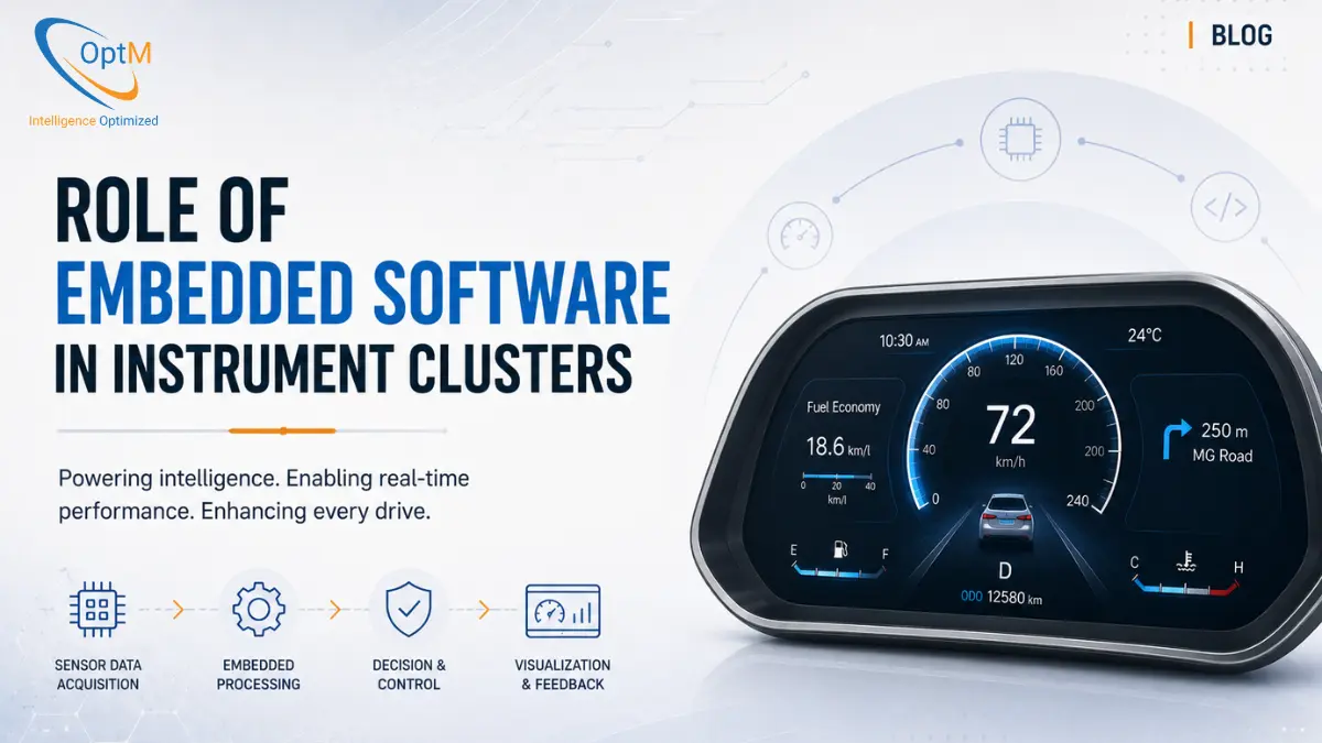
While the physical hardware provides the processing boundaries, it is the underlying code that defines the system's speed, reliability, and safety. This guide provides an exhaustive breakdown of the role of embedded software in instrument clusters, tracing the exact architecture from low-level silicon drivers up to the high-performance graphics engines that render the final pixel.
What Is the Role of Embedded Software in an Instrument Cluster?
Embedded software in an instrument cluster acts as the critical bridging intelligence between raw vehicle hardware and the visual display. It consists of Board Support Packages (BSPs) that initialize the silicon, deterministic Real-Time Operating Systems (RTOS) that guarantee microsecond-level execution of safety alerts, and cross-platform vector graphics engines like Qt that render the fluid Human-Machine Interface (HMI) at 60 frames per second.
Before diving into the code structure, it is highly recommended to understand the physical foundation it runs on. Review our complete guide on what is an instrument cluster to contextualize the hardware constraints.
The Market Reality: Code Complexity in 2026
The automotive industry is undergoing an unprecedented software explosion. According to industry analysis by Statista and Focus2Move, the average software-defined vehicle in 2026 operates on roughly 650 million lines of code, up from just 100 million a decade ago.
Managing this complexity within the confined space of a dashboard requires a highly modular, multi-layered software stack. If the code is monolithic, a single memory leak in the media player could crash the speedometer. To prevent this, embedded engineers design the software architecture in strictly isolated vertical layers.
1. The Foundation: Board Support Packages (BSP) and the HAL
A consumer operating system (like Windows) is designed to run on millions of different hardware configurations. Automotive embedded software, conversely, is hyper-optimized for one highly specific, custom-built circuit board.
Bootloaders and Board Initialization
The journey of the embedded software begins the millisecond the vehicle receives ignition voltage. The primary bootloader—stored in ultra-fast NOR flash memory—wakes up the System-on-Chip (SoC). Its job is minimal but vital: initialize the RAM, set the primary CPU clock frequencies, and load the core operating system into memory.
The Board Support Package (BSP)
Because every OEM utilizes slightly different components of instrument cluster hardware, embedded engineers must write a custom Board Support Package (BSP). The BSP contains the low-level device drivers tailored exclusively to that specific board. It tells the processor exactly how to talk to the specific Power Management IC (PMIC), the display timing controller, and the CAN transceivers.
The Hardware Abstraction Layer (HAL)
Sitting just above the BSP is the Hardware Abstraction Layer (HAL). The HAL serves as a universal translator. When understanding how instrument cluster works, it is the HAL that captures the chaotic, raw hexadecimal voltage pulses from the vehicle's network and translates them into clean, standardized variables (e.g., Speed = 65.5 km/h). By abstracting the physical hardware, the HAL ensures that if an OEM changes a physical sensor mid-production, the upper graphical software does not need to be rewritten.
2. Operating Systems: The RTOS vs. HLOS Divide
Once the hardware is initialized, the system must execute the logic. However, an instrument cluster must simultaneously perform two fundamentally different tasks: rendering rich 3D infotainment and guaranteeing the instant display of life-or-death safety warnings.
Because one OS cannot perfectly handle both tasks simultaneously, a modern instrument cluster architecture utilizes a dual-OS approach, separated by a bare-metal Type-1 Hypervisor.
The Real-Time Operating System (RTOS)
Safety-critical functions of instrument cluster systems—such as displaying the speedometer, ABS warning lights, and ADAS collision alerts—run on a deterministic RTOS (such as QNX or Green Hills INTEGRITY).
An RTOS operates on absolute time predictability. Embedded engineers write strict thread prioritization algorithms. If the CAN bus receives an airbag deployment signal (Priority Level 1) while the system is updating the trip odometer (Priority Level 2), the RTOS hard-scheduler instantly preempts the odometer calculation, ensuring the critical airbag warning is rendered within single-digit microseconds.
The High-Level Operating System (HLOS)
For non-critical tasks that require rich graphics—such as 3D turn-by-turn navigation mapping, media album art, and complex cloud connectivity—the system runs a High-Level OS, typically Embedded Linux or Android Automotive. While Linux cannot guarantee the strict microsecond deadlines of an RTOS, it possesses the massive software libraries required to handle complex multimedia pipelines.
3. Communication and Network Protocol Logic
An instrument cluster is completely blind without a continuous feed of data from the rest of the vehicle. Managing this data influx is one of the most critical responsibilities of the embedded software.
Achieving seamless instrument cluster integration with ECUs, sensors and vehicle networks requires the software to decode multiple networking protocols simultaneously:
- CAN and CAN FD Parsing: The software utilizes network matrix databases (.DBC files) to extract multiplexed payloads from the Controller Area Network. It verifies the Cyclic Redundancy Check (CRC) of every incoming packet to ensure no data was corrupted by electromagnetic interference.
- J1939 Protocol Stack: In commercial heavy-duty trucks, the software must process J1939 messages, decoding specific Parameter Group Numbers (PGNs) to display engine retardation or diesel exhaust fluid levels.
- Automotive Ethernet: For massive data streams, such as live 360-degree camera feeds or streaming navigation data from the central infotainment unit, the embedded software utilizes TCP/IP stacks over high-speed unshielded twisted pair connections.
4. The Graphics Engine: Qt/QML and Hardware Acceleration
The ultimate deliverable of the software stack is the pixel on the screen. Translating network data into a fluid, anti-aliased visual interface requires massive computational power.
Legacy systems used pre-rendered, static bitmap images. If a needle rotated, the system simply cycled through 100 different pictures of a needle. This was incredibly memory-intensive and looked visually jagged.
The Vector Rendering Pipeline
Today, premium instrument cluster UI/UX design relies on dynamic vector graphics, built predominantly on the cross-platform Qt and QML frameworks.
Instead of loading static images, the QML logic dynamically calculates the exact geometry of the speedometer needle based on the incoming CAN telemetry. The Qt application then issues draw calls directly to the SoC’s Graphics Processing Unit (GPU) using OpenGL ES or Vulkan APIs. The GPU computes the shading, applies anti-aliasing, and rasterizes the vector math into a 2D pixel grid.
This direct hardware acceleration allows the embedded software to render sweeping needle animations and complex layout transitions at a locked 60 frames per second (fps). Dropping below 60fps causes visible stuttering, which drastically increases driver eye fatigue.
5. Functional Safety (ISO 26262) and Redundancy Logic
Because the dashboard is the primary safety interface of the vehicle, the embedded software must comply with ISO 26262 standards, typically achieving ASIL B (Automotive Safety Integrity Level) compliance for general readouts and ASIL C for critical telltales.
To achieve this, the software is engineered with severe paranoia. It assumes that hardware will eventually fail and builds logical redundancies to mitigate that failure.
Inter-Process Communication (IPC) and Shared Memory
Because the RTOS and the Linux HLOS are walled off by the hypervisor, they cannot directly share memory. If the driver changes the drive mode to "Sport," the RTOS registers the mechanical button press, but the Linux OS needs to know so it can change the background graphics to red. Embedded engineers build strictly regulated, encrypted Inter-Process Communication (IPC) channels. The RTOS writes a flag to a secured memory block, which the Linux partition reads milliseconds later to execute the graphic change.
The Watchdog Timer
The ultimate software failsafe is the Watchdog loop. A small, independent safety microcontroller continuously runs a background loop demanding a "heartbeat" from the main SoC's graphics engine. If the main SoC freezes due to a memory leak, it misses the heartbeat. The safety microcontroller’s software immediately detects this, triggers a hard reboot of the main SoC, and bypasses the dead graphics pipeline to manually illuminate the physical LED warning lights on the cluster bezel.
Validating these failsafes requires thousands of hours of destructive simulation. To understand the exact software testing frameworks utilized, explore our methodology on digital instrument cluster testing and validation.
6. Engineering Constraints and Software Optimization
Writing embedded software for a vehicle requires navigating strict physical realities that desktop software developers never encounter. Overcoming these limitations represents the core of the challenges in instrument cluster development.
The Sub-Second Boot Challenge
When you start a car, the speedometer must be visible almost instantly. Federal regulations require critical telltales to illuminate within 500 milliseconds. An embedded Linux kernel typically takes 10 to 15 seconds to boot. To solve this, engineers execute intense boot-time optimizations: stripping out unnecessary kernel modules, utilizing eXecute-In-Place (XIP) flash memory, and prioritizing the loading of the display pipeline over non-essential background daemons.
Thermal Throttling Logic
Driving millions of pixels at 60fps generates massive heat from the GPU. However, the cluster is trapped inside a sealed dashboard cavity with zero airflow. The embedded software includes thermal management daemons that monitor SoC die temperatures. If the temperature exceeds safe limits, the software dynamically down-clocks the processor or slightly reduces the display's maximum brightness to prevent physical hardware meltdown.
Cybersecurity and Secure Boot
Modern clusters are connected to the cloud for Over-The-Air (OTA) updates. This introduces the risk of remote hacking. The embedded software utilizes a Hardware Security Module (HSM) on the silicon to execute a "Secure Boot." When the cluster turns on, the HSM cryptographically verifies the digital signature of the operating system. If the signature does not match the OEM's master key, the software halts the boot sequence, preventing a malicious OS from taking control of the vehicle's dashboard.
Transitioning from Concept to Automotive-Grade Reality
The role of embedded software in an instrument cluster represents the pinnacle of deterministic engineering. It is a masterclass in orchestrating high-speed graphics rendering, strict safety redundancies, and millisecond-level network protocol translation within the severe thermal and memory constraints of a vehicle cabin.
Building a compliant software stack that navigates Type-1 hypervisors, Qt-accelerated graphics, and secure OTA mechanisms requires highly specialized, cross-domain engineering bandwidth. For Tier 1 suppliers and OEMs looking to deploy ARAI-ready SDV platforms without absorbing years of developmental friction, adopting a pre-engineered display architecture is the most strategic approach.
If your organization is seeking an automotive-grade interface solution capable of flawless safety execution and premium visual fidelity, explore OptM’s production-ready Digital Instrument Cluster architecture. Our embedded systems engineering teams provide comprehensive integration support—from custom RTOS provisioning and secure boot implementation to optimized Qt HMI rendering—ensuring your next vehicle platform is intelligent, secure, and ready for mass production.
Frequently Asked Questions
What is the specific purpose of a Board Support Package (BSP) in dashboard initialization?
The BSP contains the highly specific low-level device drivers compiled for that unique board design. It initializes the core clock networks, maps the physical pin structures, and sets up communication with the onboard PMIC.
Why is the boot sequence structured into multiple distinct software phases?
To prioritize regulatory compliance. The initial boot阶段 focuses strictly on loading low-overhead code to activate warning telltales and basic metrics within milliseconds, while the heavier graphics OS completes initialization in the background.
How does the software ensure that a 3D graphic rendering task never causes a frame delay for a safety alert?
The embedded scheduler applies strict task prioritization. Safety-critical loops operate inside the deterministic RTOS domain, which instantly interrupts the high-level operating system's graphics threads whenever an emergency message arrives.
What does a watchdog daemon do if it detects a frozen user interface loop?
A watchdog core constantly tracks software "heartbeat" signals from the graphics application. If a freeze occurs and a heartbeat window is missed, the daemon triggers a hardware-level reset of the primary processor to restore functionality.
How does embedded code process network data frames securely?
The software utilizes checksum algorithms to validate data packet integration and implements message authentication systems to confirm that incoming payloads came from a verified vehicle controller, block stalling spoofing attempts.
What is 'Execute-in-Place (XIP)' software logic and why is it used?
XIP allows the processor to execute code instructions directly from non-volatile NOR flash memory instead of copying them into volatile RAM first. This significantly reduces initialization times during fast-boot cycles.
Why do thermal management software daemons down-clock processor frequencies?
When driving complex graphic pipelines at 60fps inside a sealed housing, components generate intense heat. The thermal daemon scales down clock rates or display brightness to protect the hardware from damage if limits are exceeded.