
Content Writer & SEO Specialist
Content Writer & SEO Specialist
Aditya Sharma is a content writer at OptM Solutions specializing in automotive electronics, embedded systems, telematics, electric vehicle technologies, connected mobility, and autonomous driving technologies.
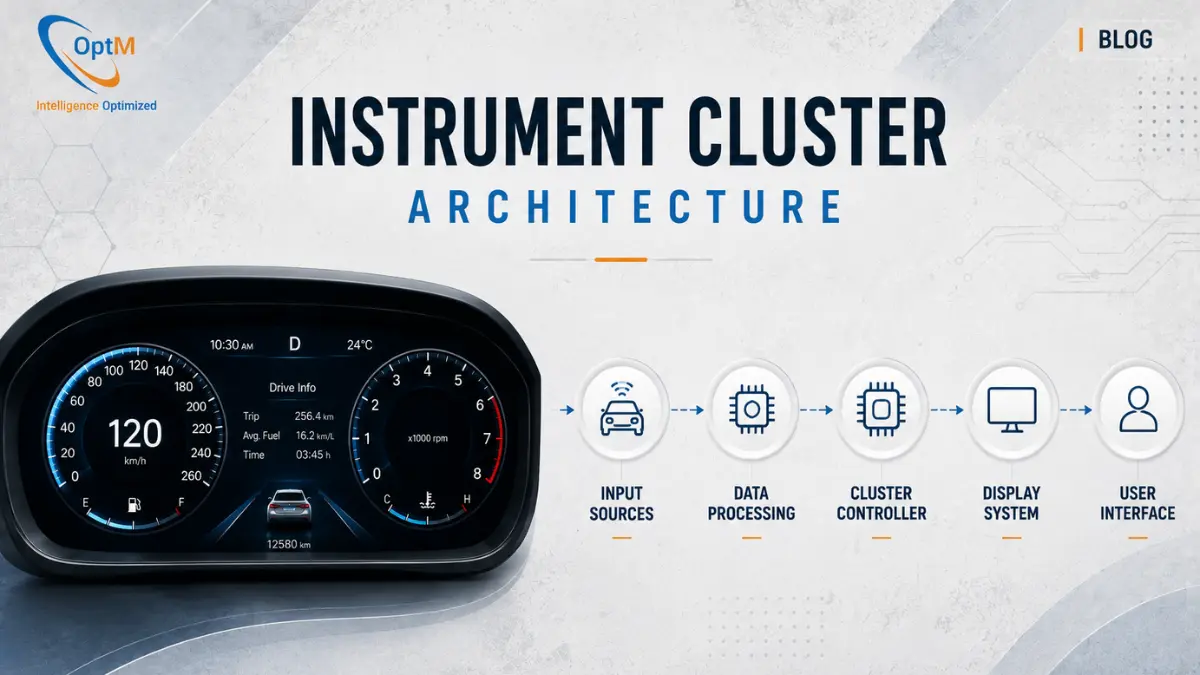
LinkedIn ProfileDeploying a reliable, latency-free digital dashboard goes far beyond mounting a high-brightness display inside a vehicle cabin. As the automotive industry pivots deeply into the era of software-defined vehicles (SDVs), the underlying instrument cluster architecture has become one of the most rigorously engineered subsystems in modern mobility. For OEMs, Tier 1 suppliers, and embedded software architects, constructing this architecture requires balancing raw graphical processing power with uncompromising functional safety.
This comprehensive engineering blueprint deconstructs the multi-layered hardware and software topology of the modern digital instrument cluster. It explores how asymmetric silicon, hardware abstraction layers, automotive hypervisors, and deterministic real-time operating systems converge to render vehicle telemetry safely at 60 frames per second without risking system collapse.
What Is Instrument Cluster Architecture?
Instrument cluster architecture is the structural framework of hardware and software layers that drives an automotive digital dashboard. It typically utilizes an Asymmetric Multi-Processing (AMP) silicon topology, pairing a high-performance System-on-Chip (SoC) for 3D graphics rendering with an isolated safety Microcontroller (MCU) to guarantee real-time execution of critical vehicle diagnostics and warning telltales.
To contextualize where this architecture fits within the broader vehicle ecosystem, we recommend first exploring our foundational guide on what is an instrument cluster.
The Evolution: From Distributed to Domain-Centralized Topology
Historically, automotive electronic architecture was heavily distributed. A vehicle featured dozens of isolated, single-function Electronic Control Units (ECUs). The braking ECU managed the brakes; the engine ECU managed the fuel injection.
However, as display fidelity increased, the sheer volume of data required to feed a digital screen overwhelmed legacy CAN buses. The architecture had to evolve.
Modern instrument cluster architecture relies on a Domain-Centralized Topology. Instead of pulling raw data from 50 different ECUs, the cluster acts as a high-performance edge node that interfaces with overarching Domain Controllers (e.g., the Powertrain Domain Controller, the ADAS Domain Controller). This shift vastly reduces network latency and wiring harness weight, allowing the cluster to focus purely on high-speed data translation and UI rendering.
1. The Core Hardware Architecture Matrix
The physical foundation of the cluster dictates its absolute processing limits. Choosing the specific components of instrument cluster hardware requires balancing the OEM's Bill of Materials (BOM) against thermal dissipation constraints.
Asymmetric Multi-Processing (AMP)
The standard hardware architecture utilizes an AMP configuration to ensure behavioral isolation.
- The Main Application SoC: A multi-core processor (such as an ARM Cortex-A series) handles the resource-intensive tasks. It manages the complex memory pipelines, executes the overarching operating system, and utilizes a dedicated GPU to drive the OpenGL or Vulkan graphics pipelines.
- The Safety Microcontroller (MCU): A smaller, deterministically programmed processor (like an ARM Cortex-R series) runs parallel to the main SoC. Operating completely independently, it is directly wired to the vehicle's high-speed CAN network and the physical LED telltales embedded in the dashboard bezel.
Hardware Watchdog Mechanisms
If the main SoC experiences a critical memory fault while rendering a 3D navigation map, it will freeze. In a consumer tablet, this requires a manual hard reboot. In an automotive cluster, a frozen speedometer is a catastrophic safety failure.
The hardware architecture solves this via a Watchdog Timer. The main SoC must send a continuous digital "heartbeat" to the safety MCU. If the MCU stops receiving this heartbeat, it instantly detects the SoC crash. While it initiates a hardware-level reset of the SoC, the safety MCU immediately bypasses the frozen graphics engine to take direct control of a separate display overlay plane, keeping critical warning lights (like engine failure or low brake fluid) continuously visible.
2. The Software Architecture Layer
Hardware is inert without a deeply optimized software stack. The role of embedded software in instrument clusters is structurally divided into secure, isolated layers to prevent minor application bugs from triggering system-wide crashes.
The Board Support Package (BSP) and HAL
The lowest tier of the software architecture is the Board Support Package (BSP). The BSP contains the highly specific bootloaders and device drivers needed to initialize the custom silicon—waking up the Power Management ICs (PMICs) and configuring the display timing controllers.
Immediately above the BSP sits the Hardware Abstraction Layer (HAL). The HAL serves as a translation barrier. When understanding how instrument cluster works, the HAL is what takes a raw, chaotic hex payload from the CAN bus and translates it into a clean floating-point variable (e.g., vehicle speed) that the upper application layers can easily read.
The Operating System (OS) Ecosystem
The cluster does not run a single operating system; it often runs two, isolated by virtualization.
- Deterministic RTOS: For safety-critical data routing, engineers deploy a Real-Time Operating System (such as QNX or INTEGRITY). An RTOS guarantees that a specific task (like an airbag deployment warning) will execute within a strictly defined microsecond window, completely preempting any non-critical tasks.
- High-Level OS (HLOS): For rich media rendering and complex UI transitions, an Embedded Linux or Android Automotive OS partition manages the graphical applications.
3. Automotive Hypervisors & Virtualization
How do two fundamentally different operating systems run securely on the same piece of silicon without corrupting each other's memory? The answer lies in Automotive Hypervisors.
A hypervisor is a highly specialized, lightweight layer of software that sits directly on the bare metal of the SoC. It virtualizes the CPU, memory, and GPU resources, splitting the SoC into multiple isolated Virtual Machines (VMs).
Type 1 Bare-Metal Hypervisors
In automotive clusters, engineers almost exclusively deploy Type 1 (Bare-Metal) Hypervisors. Because they run directly on the hardware rather than on top of a host OS, they provide the near-zero latency required for vehicular safety.
- Partition 1 (Safety Domain): Runs the RTOS, controls the speedometer data, and manages ADAS warnings.
- Partition 2 (Infotainment Domain): Runs Embedded Linux, controls the turn-by-turn navigation map and media track metadata.
If the Infotainment Linux partition suffers a fatal crash due to a corrupted media file, the Type 1 hypervisor ensures the Safety RTOS partition is entirely unaffected, continuing to render the vehicle's speed and critical alerts flawlessly.
The Market Reality: The automotive industry's pivot toward centralized computing is driving explosive demand for virtualization technologies. According to market analysis by Fortune Business Insights, the global automotive hypervisor market size is projected to grow from $557.9 million in 2026 to over $6.69 billion by 2034, registering a massive Compound Annual Growth Rate (CAGR) of 36.4%.
4. Inter-Process Communication (IPC) and Memory Management
Because the hypervisor physically walls off the virtual machines, they cannot natively share data. However, the driver expects a unified interface. If the driver changes the vehicle into "Sport Mode" via a physical dial (handled by the RTOS), the graphics engine (handled by Linux) needs to know instantly so it can change the dashboard colors from blue to red.
Shared Memory and IPC
To solve this, the architecture utilizes Inter-Process Communication (IPC) protocols. The hypervisor creates a strictly regulated "shared memory" pool. The RTOS writes the "Sport Mode = True" variable into this pool. The Linux OS reads that variable microseconds later and triggers the graphical transition. This IPC framework is heavily encrypted and protected by Memory Management Units (MMUs) to ensure one OS cannot accidentally overwrite the critical memory blocks of the other.
5. Graphics Architecture: The Qt Rendering Pipeline
Translating network data into a fluid, anti-aliased visual interface requires a massive architectural effort. Legacy automotive systems relied on static bitmaps, which were heavy on memory and looked jagged when rotated.
Modern cluster architectures utilize dynamic vector-graphics engines, predominantly built upon the cross-platform Qt and QML frameworks.
- State Management: The Qt application layer receives the telemetry data (e.g., RPM = 4500).
- Vector Calculation: The QML logic dynamically calculates the exact geometry required to rotate the virtual tachometer needle to the correct angle.
- Hardware Acceleration: The Qt framework issues draw calls directly to the SoC's GPU. The GPU computes the shading, lighting, and anti-aliasing required to make the needle look three-dimensional.
- Display Output: The rasterized frame is pushed to the frame buffer, updating the screen without taxing the main CPU.
Maintaining a flawless 60fps refresh rate while rendering 3D assets inside a sealed dashboard cavity generates intense heat. Overcoming these thermal limitations remains one of the primary challenges in instrument cluster development.
6. Functional Safety (ISO 26262) & ASIL Compliance
Because an instrument cluster acts as the primary communication medium for vehicle safety, its architecture must comply with stringent international standards, specifically ISO 26262.
ISO 26262 classifies components by their Automotive Safety Integrity Level (ASIL), ranging from ASIL A (lowest risk) to ASIL D (highest risk).
The instrument cluster generally targets ASIL B compliance for the main display, but specific warning indicators (like brake system failure or steering column faults) often require the strict determinism of ASIL B to ASIL C architectures.
To achieve this, the architecture must prove that no single point of failure can lead to an unsafe state. This dictates the necessity of the asymmetric SoC-MCU hardware split, the implementation of Watchdog Timers, and the deployment of Type 1 hypervisors. Before an architecture is approved for mass production, it must pass destructive Hardware-in-the-Loop (HIL) stress testing to validate these fail-safes. For a detailed look at these methodologies, review our guide on digital instrument cluster testing and validation.
7. Resolving Security Architecture: Hardware Security Modules (HSM)
As digital clusters evolve to support Over-The-Air (OTA) firmware updates and display connected cloud data, they become highly vulnerable attack surfaces. If a bad actor gains access to the cluster's network, they could spoof safety warnings or send malicious CAN frames back into the powertrain.
Modern cluster architecture incorporates dedicated Hardware Security Modules (HSMs) directly onto the silicon die of the primary processor.
- Secure Boot: When the vehicle turns on, the HSM cryptographically verifies the digital signature of the cluster's operating system. If the OS has been tampered with, the HSM halts the boot sequence.
- Encrypted Storage: The HSM acts as a vault, storing all cryptographic keys and vehicle certificates away from the main operating system where hackers cannot access them.
- Message Authentication: When the cluster receives a CAN frame telling it to update its firmware, the HSM validates the MAC (Message Authentication Code) to prove the command actually originated from the OEM's cloud server.
Accelerating Production-Grade Cockpit Architectures
Designing an automotive digital instrument cluster architecture requires a masterful synchronization of highly complex subsystems. From configuring bare-metal Type 1 hypervisors to orchestrating flawless IPC memory handovers and rendering dynamic Qt-based vector graphics, the engineering bandwidth required to build these deterministic platforms from scratch is immense.
For Tier 1 suppliers and automotive OEMs aiming to bypass years of developmental friction, adopting a pre-engineered, ARAI-ready foundational platform is the most strategic path to market.
If your organization is looking to integrate scalable, ASIL-compliant display topologies into your next generation of software-defined vehicles, explore OptM's production-ready Digital Instrument Cluster solutions. Our embedded engineering teams provide end-to-end architectural design—ranging from ruggedized hardware integration to custom RTOS prioritization—ensuring your in-cabin technology delivers uncompromised safety and performance.
Frequently Asked Questions
Why is a Type 1 Bare-Metal Hypervisor used instead of a standard hosted hypervisor?
Type 1 hypervisors run directly on the underlying silicon hardware with near-zero software layer overhead. Hosted hypervisors run on top of an existing operating system, introducing processing delays that are unacceptable for deterministic automotive systems.
What happens if the high-level infotainment domain crashes due to a software bug?
The Type 1 hypervisor ensures complete separation. Because the safety-critical metrics run in an isolated partition, a crash in the media or navigation domain will not disrupt the real-time display of speed and warning indicators.
How do isolated operating systems communicate with each other through the hypervisor?
They utilize highly restricted Inter-Process Communication (IPC) channels. The hypervisor provisions a secure shared memory pool where one partition can write state variables that the other reads within microsecond windows.
What is the practical value of a Domain-Centralized Topology for dashboard networks?
It replaces older setups where dozens of individual ECUs streamed uncoordinated messages. Instead, domain controllers aggregate local data and route it via centralized backbones, reducing wiring harness weights and bus latencies.
How does the Hardware Abstraction Layer (HAL) future-proof an OEM's production line?
The HAL isolates the core application code from low-level hardware dependencies. If an internal component or transceiver is swapped due to supply chain changes, only the HAL layer requires updates; the primary UI code remains untouched.
What is a 'Memory Management Unit (MMU)' constraint in safety partitioning?
The MMU enforces physical boundaries on memory access. It prevents non-safety code from accidentally writing into memory addresses reserved for the real-time system, blocking errors like pointer overrides from corrupting safety parameters.
Why are cryptographic keys managed within a dedicated Hardware Security Module (HSM)?
The HSM operates on an independent hardware root of trust separate from the primary application cores. This prevents malware or an exploit in the infotainment partition from accessing or stealing the vehicle's master identity keys.