
Content Writer & SEO Specialist
Content Writer & SEO Specialist
Aditya Sharma is a content writer at OptM Solutions specializing in automotive electronics, embedded systems, telematics, electric vehicle technologies, connected mobility, and autonomous driving technologies.
LinkedIn ProfileWhen evaluating the Bill of Materials (BOM) for a modern software-defined vehicle, the digital dashboard represents one of the most structurally complex and highly integrated subsystems on the production line. Moving beyond the legacy era of mechanical gauges and dedicated stepper motors, today's automotive display units are highly sophisticated edge-computing nodes. They demand automotive-grade silicon, multi-layered embedded software, and ruggedized physical enclosures capable of surviving extreme vehicular environments.
For Tier 1 suppliers and OEM procurement teams, understanding exactly what goes into the system is vital for balancing manufacturing costs against rigorous functional safety requirements. This definitive engineering guide deconstructs the hardware, silicon, and software components that power the modern automotive instrument cluster, offering a comprehensive look at the foundation of in-cabin vehicle intelligence.
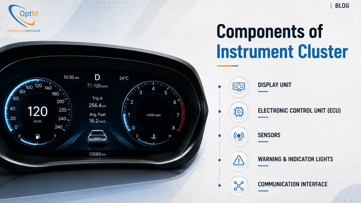
Components of an Instrument Cluster
The hardware components of an instrument cluster consist of an automotive-grade display panel, a high-performance System-on-Chip (SoC) for graphical processing, an isolated safety Microcontroller (MCU), high-speed memory modules, Power Management ICs (PMICs), and network transceivers. These components are mounted on a multi-layer custom Printed Circuit Board (PCB) and housed within an IP65/IP67-rated thermal enclosure to ensure stable, real-time vehicle diagnostics rendering.
To fully grasp why these specific components are selected over consumer-grade electronics, it is helpful to establish a baseline understanding of exactly what is an instrument cluster and how its role has evolved into the central safety terminal of the vehicle.
1. The Visual Layer: Automotive-Grade Display Panels
The most visible component of the cluster is the display panel. Unlike consumer tablets or smartphone screens, automotive displays must guarantee continuous luminance and structural integrity across a harsh thermal matrix, typically ranging from -40°C to +85°C.
TFT-LCD vs. OLED Technologies
According to Mordor Intelligence, the global automotive display market size stood at $27.95 billion in 2026, with liquid-crystal displays (LCD) commanding over 65% of the market share.
- TFT-LCD (Thin-Film Transistor Liquid Crystal Display): This remains the dominant technology for mass-market vehicle clusters due to its cost-efficiency, proven thermal reliability, and high-brightness capabilities (often exceeding 1000 nits). Advanced variations, such as Low-Temperature Polysilicon (LTPS) LCDs, are increasingly utilized to achieve higher pixel densities and thinner bezels.
- OLED (Organic Light-Emitting Diode): As manufacturing costs stabilize, OLEDs are penetrating the premium EV segment. Because OLED pixels emit their own light, they do not require a separate backlight array. This allows for perfect, true-black contrast ratios—crucial for nighttime driving—and enables flexible or curved dashboard topologies.
Optical Enhancements and Surface Treatments
An instrument cluster cannot succumb to sun glare or fingerprint smudging. Display engineers apply sophisticated surface treatments to the outer cover glass:
- Anti-Glare (AG) Etching: Microscopically diffuses direct sunlight hitting the dashboard to prevent blinding reflections.
- Anti-Reflective (AR) Coating: Reduces the internal reflection between the display matrix and the cover glass, enhancing contrast and color saturation.
- Optical Bonding: A layer of transparent optical resin is injected between the LCD panel and the cover glass, eliminating the air gap. This prevents condensation buildup and drastically improves structural shock resistance.
2. The Processing Core: Systems-on-Chip (SoC) and Microcontrollers
The intelligence of the dashboard resides on the silicon level. The complexity of how instrument cluster works is rooted in its ability to process millions of calculations simultaneously without crashing. This requires an Asymmetric Multi-Processing (AMP) architecture.
The Main Application Processor (SoC)
The heavy lifting is performed by a high-frequency System-on-Chip. These processors generally feature a multi-core ARM Cortex-A architecture. The SoC handles the heavy computational loads: booting the primary operating system, decompressing complex graphical assets, managing the infotainment multimedia pipelines, and executing the vector-based rendering logic.
Crucially, the SoC integrates a dedicated Graphics Processing Unit (GPU). The GPU provides the hardware acceleration necessary to drive OpenGL ES or Vulkan APIs, ensuring that graphical transitions, such as a sweeping tachometer needle, render smoothly at 60 frames per second.
The Safety Microcontroller (MCU)
Relying solely on a complex SoC for safety-critical data is a severe functional safety risk. If the SoC experiences a memory leak and the OS freezes, the driver would lose vital speed and braking alerts.
To achieve ISO 26262 ASIL (Automotive Safety Integrity Level) compliance, the main SoC is paired with an independent, deterministically programmed safety MCU (typically an ARM Cortex-R or Cortex-M series). This MCU directly monitors the vehicle's CAN bus for critical fault flags. Operating on a robust RTOS, the MCU runs parallel to the SoC. If the main SoC crashes, the safety MCU bypasses it entirely to illuminate hard-wired LED warning telltales (e.g., ABS fault, airbag deployment) embedded in the bezel.
3. Embedded Memory Architectures
Real-time processing requires highly optimized data storage and retrieval. Automotive memory must withstand intense vibration and vast temperature fluctuations without experiencing bit-flip errors.
- LPDDR4 / LPDDR5 RAM: Low-Power Double Data Rate Synchronous Dynamic Random Access Memory provides the vast, high-bandwidth memory pipelines required by the GPU's frame buffers. When the driver cycles the ignition, the operating system and graphical assets are loaded into RAM to ensure millisecond-level responsiveness.
- eMMC and UFS Storage: Embedded Multi-Media Card (eMMC) or Universal Flash Storage (UFS) modules provide non-volatile storage for the operating system kernel, the root file system, graphical texture files, and network routing databases (.DBC files).
- NOR Flash: Used for executing code directly in place (eXecute In Place - XIP). NOR Flash holds the primary secure bootloader. Because of its extreme read speeds, it ensures the cluster begins its boot sequence the exact millisecond the vehicle receives terminal wake-up voltage.
4. Power Management and Environmental Protection
A vehicle's electrical network is a volatile environment. Alternator fluctuations, starter motor cranking, and high-voltage load dumps from hybrid powertrains create extreme voltage spikes that would instantly destroy consumer silicon.
Power Management ICs (PMIC)
The PMIC acts as the electrical gatekeeper. It takes the unregulated, fluctuating 12V or 24V supply from the vehicle harness and steps it down into multiple tightly regulated DC voltage rails (e.g., 5V, 3.3V, 1.8V, 1.2V). These rails independently feed the SoC, the memory modules, the display backlight drivers, and the transceivers.
Thermal Regulation Frameworks
Processing high-resolution graphics generates significant thermal energy, yet the cluster is sealed inside an unventilated dashboard cavity. Dissipating this heat without utilizing mechanical cooling fans (which introduce noise and mechanical failure points) is a primary hurdle when navigating challenges in instrument cluster development. Engineers utilize advanced passive cooling techniques, integrating heavy aluminum die-cast heat sinks directly against the SoC thermal pads and utilizing custom thermal vias within the PCB to wick heat away from the silicon.
5. Communication Interfaces and Transceivers
The cluster relies on continuous data feeds from the powertrain, the body control module, and external radar arrays. Flawless instrument cluster integration with ECUs, sensors and vehicle networks is achieved through specialized physical transceivers mounted on the board.
- CAN and CAN FD Transceivers: The Controller Area Network transceivers translate the differential voltages on the physical wire into the digital Rx/Tx bitstream required by the microcontroller. CAN FD (Flexible Data-rate) allows for larger payloads, accommodating the data density of modern EVs.
- Automotive Ethernet (100BASE-T1 / 1000BASE-T1): As dashboards begin displaying high-resolution surround-view camera feeds and dense navigation maps, the bandwidth limits of CAN are quickly exceeded. Automotive Ethernet provides high-throughput, low-latency data pipelines over single unshielded twisted pair cables, reaching speeds of 1 Gbps.
- LIN (Local Interconnect Network): A lower-cost serial network used for non-critical, low-speed communications, such as reading steering wheel button inputs or adjusting the dashboard backlight dimming parameters.
6. The Mechanical Foundation: PCB Assembly and Rugged Enclosures
The electronic components are physically united on a custom Printed Circuit Board (PCB). Automotive PCBs are highly specialized multi-layer designs (often 6 to 12 layers) engineered for strict Electromagnetic Compatibility (EMC).
EMI Shielding
The cluster operates in close proximity to massive electrical motors, ignition coils, and high-frequency wireless modems. The PCB layout uses strategic ground planes and metallic Faraday cages over sensitive components to prevent Electromagnetic Interference (EMI) from corrupting data signals, while also ensuring the cluster itself does not emit radiation that could disrupt the vehicle's radio.
IP65/IP67 Rugged Enclosures
The finalized board and display assembly are enclosed within robust polycarbonate or die-cast aluminum housings. These enclosures are engineered to meet strict ingress protection ratings, utilizing custom silicon gaskets to prevent moisture condensation, fine particulate dust, and harsh chemical cleaning agents from reaching the logic board.
Validating these physical components requires exhaustive stress cycles. For a detailed look into the destructive thermal and vibration cycles these enclosures must survive, refer to our comprehensive methodology on instrument cluster testing and validation.
7. The Software Stack: BSPs, RTOS, and Middleware
Hardware is inert without an optimized software framework. A highly structured instrument cluster architecture segregates the software into distinct, isolated layers to prevent system-wide failures.
The embedded software in instrument clusters begins at the Board Support Package (BSP). The BSP contains the low-level device drivers that allow the operating system to interface with the unique silicon components—configuring the display timing controllers, initializing the PMIC registers, and setting up the CAN baud rates.
Above the hardware abstraction layer sits the Operating System. Safety-critical parameters run on deterministic Real-Time Operating Systems (RTOS) like QNX or INTEGRITY, which guarantee task execution within specific microsecond windows. Non-critical infotainment features (like media browsing) often run on a parallel Embedded Linux or Android Automotive partition. Hypervisor software is used to securely partition the SoC's hardware resources between these two distinct OS environments.
8. The Human-Machine Interface (HMI) Graphic Engine
The final component is the visual layer that the driver interacts with. Premium instrument cluster UI/UX design relies heavily on cross-platform C++ frameworks, most notably the Qt and QML environment.
Instead of relying on heavy, static image files, the Qt framework allows UI designers to build fluid, vector-based interfaces. When the vehicle accelerates, the underlying QML logic recalculates the geometry of the virtual speedometer needle and pushes those coordinate changes directly to the SoC's GPU. This hardware-accelerated pipeline is what allows modern digital clusters to achieve a flawless, anti-aliased 60fps refresh rate, eliminating the visual stuttering that contributes to driver fatigue.
Partnering for Next-Generation Cockpit Deployment
The hardware and software components detailed above create a highly capable, localized edge-processing hub. However, in modern fleet and connected vehicle ecosystems, the diagnostic intelligence generated by the instrument cluster—such as battery degradation alerts, ADAS fault codes, and extreme RPM telemetry—must not remain trapped inside the cabin.
To fully monetize vehicle data, OEMs and fleet operators must route this rich telemetry from the dashboard directly to the enterprise cloud. This requires pairing your in-cabin display hardware with a robust, LTE-enabled cellular gateway capable of ultra-low latency data transfer.
If your engineering team is evaluating production-ready architectures to bridge high-speed vehicle networks with scalable cloud analytics, explore the enterprise-grade integration capabilities of OptM's Digital Instrument Cluster. Together with our comprehensive display solutions, it forms the definitive foundation for next-generation connected mobility.
Frequently Asked Questions
Why do digital instrument clusters feature an asymmetric dual-core processor topology?
This setup separates processing responsibilities. The high-frequency Application Processor (SoC) handles heavy graphics loops, while an independent safety Microcontroller (MCU) operates a real-time system to monitor CAN transceivers and keep critical warning indicators functional.
What is 'optical bonding' and why is it critical for automotive screens?
Optical bonding fills the internal air gap between the display panel and the front cover glass with an optical-grade resin. This prevents internal condensation buildup, limits reflections from sunlight, and improves the screen's resistance to physical shocks.
How do Power Management ICs (PMICs) protect the cluster from a 'load dump'?
A load dump occurs when the battery disconnects while the alternator is generating current, creating a massive voltage spike. The automotive-grade PMIC clamps these extreme surges and filters the inputs to maintain stable, low-voltage DC rails for the internal silicon.
When is Automotive Ethernet preferred over a standard CAN or CAN FD transceiver?
Automotive Ethernet is required when the data payload demands gigabit-per-second speeds, such as streaming uncompressed 360-degree camera feeds, complex ADAS mapping displays, or high-definition navigation tiles.
What is the role of NOR Flash memory within the memory architecture?
NOR Flash features exceptionally fast read access and supports Execute-In-Place (XIP) workflows. It holds the initial secure bootloader code, enabling the system to begin its processing sequence within a fraction of a millisecond.
Why do automotive PCBs require specific ground planes and Faraday cages?
Faraday cages and dedicated PCB ground planes shield sensitive internal traces from high-frequency electromagnetic interference (EMI) emitted by ignition coils or electric traction motors, ensuring compliance with strict EMC standards.
What distinguishes an IP65 housing from an IP67 housing in dashboard engineering?
An IP65-rated housing protects the internal circuit board against airborne dust and low-pressure water sprays. An IP67 housing provides identical dust protection but adds submersible sealing against water ingress during severe moisture exposure.