
Content Writer & SEO Specialist
Content Writer & SEO Specialist
Aditya Sharma is a content writer at OptM Solutions specializing in automotive electronics, embedded systems, telematics, electric vehicle technologies, connected mobility, and autonomous driving technologies.
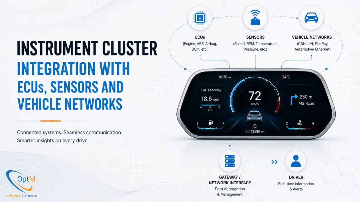
LinkedIn ProfileIn the architecture of a software-defined vehicle (SDV), no component exists in isolation. A modern digital dashboard is a highly capable edge-processing hub, but it is entirely blind without a continuous, deterministic feed of data from the rest of the vehicle. Achieving flawless instrument cluster integration with ECUs, sensors and vehicle networks is arguably the most complex phase of automotive embedded engineering.
If you are an automotive OEM, Tier 1 supplier, or embedded systems architect, navigating this integration means harmonizing legacy low-speed networks with ultra-high-speed ethernet backbones, translating thousands of multiplexed sensor signals, and ensuring that life-saving ADAS warnings render with zero frame drops. This definitive 2026 engineering guide deconstructs the protocols, middleware architectures, and hardware abstraction layers required to seamlessly integrate the digital cockpit into the broader vehicle ecosystem.
What Is Instrument Cluster Integration?
Instrument cluster integration is the engineering process of bridging a vehicle's central display node with distributed Electronic Control Units (ECUs) and environmental sensors via in-vehicle networks. It involves translating diverse communication protocols—such as CAN, J1939, LIN, and Automotive Ethernet—through specialized hardware abstraction layers so that raw, high-frequency telemetry can be rendered instantly as graphical human-machine interfaces.
To fully understand the foundational display hardware executing these incoming signals, it is highly recommended to review our core primer on what is an instrument cluster.
1. The Core Challenge: Navigating the In-Vehicle Data Deluge
The sheer volume of data flowing through a modern vehicle network is staggering. According to industry analysis, a modern connected vehicle can generate up to 25 gigabytes of data every single hour, pulling information from over 100 distinct data points including external ADAS sensors, internal cameras, and powertrain diagnostics.
The instrument cluster must act as the primary filter for this data deluge. It cannot simply ingest everything; it must selectively parse, prioritize, and process specific packets without overloading its internal processors.
The Shift to Domain-Centralized Topology
Historically, integration was straightforward: dedicated analog wires ran from a specific sensor directly to the back of the dashboard gauge. As features expanded, this point-to-point wiring added hundreds of pounds to the vehicle chassis.
Today's vehicles utilize a Domain-Centralized network topology. Instead of 100 isolated ECUs broadcasting chaotic data, the vehicle is divided into domains (e.g., the Powertrain Domain, the ADAS Domain, the Infotainment Domain). The instrument cluster serves as a primary edge node within the interior/cockpit domain. Understanding how instrument cluster works in this context reveals that its primary role is to listen to the network bus, grab the specific data packets it needs, and discard the rest instantly.
2. The Protocol Ecosystem: CAN, J1939, and Automotive Ethernet
Achieving true interoperability means speaking multiple languages simultaneously. An automotive cluster is rarely integrated using a single networking standard. The physical components of instrument cluster hardware must include diverse transceivers to interface across multiple protocol environments.
The Controller Area Network (CAN & CAN FD)
The Controller Area Network (CAN) remains the undisputed backbone of automotive telemetry. It is a differential two-wire bus that allows ECUs to communicate without a host computer.
- High-Speed CAN (500 kbps): Used for standard powertrain telemetry, such as wheel speed and engine temperature.
- CAN FD (Flexible Data-Rate): As EVs demand denser data payloads, CAN FD allows for payloads of up to 64 bytes per frame (compared to standard CAN's 8 bytes), while pushing transmission speeds up to 5 Mbps.
The SAE J1939 Standard for Commercial Fleets
If you are developing a cluster for a heavy-duty commercial truck or a logistics fleet, standard CAN is insufficient. You must integrate the SAE J1939 protocol. J1939 sits on top of the physical CAN layer but utilizes a highly specialized addressing system based on Parameter Group Numbers (PGNs). This allows the cluster to read complex diesel engine diagnostics, air-brake pressures, and trailer connectivity metrics.
Automotive Ethernet (100BASE-T1 / 1000BASE-T1)
CAN and J1939 are perfect for transmitting small, numerical data (like RPM = 3000). However, they lack the bandwidth to transmit video.
Modern clusters are increasingly required to display dense, high-resolution turn-by-turn navigation maps rendered by the central infotainment unit, or live 360-degree camera feeds. Integrating these features requires Automotive Ethernet, which provides uncompressed, ultra-low latency data pipelines over single unshielded twisted pair cables, reaching speeds of 1 Gbps.
3. Bridging the Gap: The Hardware Abstraction Layer (HAL)
A network protocol is just a delivery mechanism. When a CAN frame arrives at the cluster, it is merely a string of raw hexadecimal voltages. The cluster must translate that into a usable number. This translation is governed by the role of embedded software in instrument clusters.
Network Matrix Databases (.DBC and .ARXML files)
Automotive OEMs maintain strict network databases that define exactly what every bit of data on the network means.
When the cluster's physical transceiver receives a CAN payload, the low-level embedded software utilizes a Hardware Abstraction Layer (HAL) to decode it. The HAL applies the OEM's database logic to the raw hex string:
- Extract the raw bytes from the data field.
- Apply a specific mathematical scaling factor.
- Apply the baseline offset.
The HAL then hands a clean, standardized variable (like "Speed = 72 km/h") up to the operating system. By decoupling the hardware from the software, the HAL ensures that if an OEM changes the brand of the wheel-speed sensor during production, the upper graphical software of the cluster does not need to be rewritten.
4. Multi-System Communication Interoperability
A digital dashboard is defined by its ability to synthesize data from vastly different vehicle domains and present a unified picture to the driver.
Integration with the Powertrain and EV Battery Management
The cluster maintains a continuous, high-priority handshake with the powertrain controller. For electric vehicles, this integration extends directly to the Battery Management System (BMS). The cluster does not merely read a voltage level; it aggregates localized battery cell thermal limits, regenerative braking status, and active HVAC load to run edge-processed algorithms that calculate dynamic driving range. Executing this flawlessly is one of the primary functions of instrument cluster systems in modern EVs.
Integration with ADAS and Sensor Fusion
As Advanced Driver Assistance Systems (ADAS) mature, the cluster must act as the visual terminal for external sensor arrays.
When the front-facing radar detects a sudden obstacle, it sends a spatial coordinate payload to the ADAS Domain Controller. The Domain Controller processes the collision risk and broadcasts a priority-one interrupt frame on the network.
The cluster's RTOS intercepts this frame and immediately preempts non-critical tasks to flash a high-contrast collision warning in the driver's direct line of sight.
5. Memory Pooling and Inter-Process Communication (IPC)
Because the cluster is handling safety-critical braking alerts (which must never fail) alongside heavy 3D navigation maps, the underlying instrument cluster architecture relies on a dual-OS setup. A Type-1 bare-metal hypervisor splits the System-on-Chip (SoC) into two distinct virtual machines: a deterministic RTOS for safety, and an Embedded Linux partition for graphics.
However, the driver expects these two isolated systems to act as one. If the driver activates a physical switch for "Sport Mode" (handled by the RTOS), the graphics engine (handled by Linux) needs to instantly shift the dashboard color palette from blue to red.
The IPC Framework
To solve this, embedded engineers design highly secure Inter-Process Communication (IPC) channels. The hypervisor provisions a small, encrypted block of "Shared Memory." The RTOS writes a specific flag (e.g., DriveMode_Sport = 1) into this memory pool. Milliseconds later, the Linux partition reads that flag and triggers the graphical transition within the Qt rendering engine.
Mastering this IPC synchronization without causing memory leaks or kernel panics is the core secret behind premium, lag-free instrument cluster UI/UX design.
6. Overcoming Bandwidth Collisions and Safety Prioritization
With so much data converging on a single hardware node, preventing data bus collisions is a daily reality for embedded network engineers. Resolving these bottlenecks represents one of the most difficult challenges in instrument cluster development.
CAN Arbitration and Payload Prioritization
If the media player tries to update the album art at the exact same millisecond that the ABS module reports a total brake failure, the network cannot drop the safety alert.
CAN networks solve this via physical arbitration based on the message identifier. Lower numerical IDs denote higher priority. The OEM's network engineers assign the lowest possible IDs to airbag and braking frames. The cluster's hardware transceivers are configured with strict acceptance filters, programmed to process low-ID frames instantly while buffering or ignoring high-ID infotainment frames during heavy network traffic.
7. Validating Network Stability Under Stress
Because software integration spans multiple third-party ECUs, an instrument cluster cannot be signed off for production simply because the code compiles. It must be brutally stress-tested against simulated network chaos.
During rigorous digital instrument cluster testing and validation, the cluster is hooked into Hardware-in-the-Loop (HIL) simulation racks. Test engineers bombard the cluster's physical transceivers with thousands of corrupted CAN frames, simulate sudden voltage drops, and intentionally spoof network messages to see if the cluster's security firewalls and software watchdogs can maintain operational stability and keep critical indicators illuminated.
Furthermore, as digital clusters gain Over-The-Air (OTA) update capabilities, ensuring that OTA payloads do not overwrite critical safety software adds a massive layer of cryptographic complexity to the network integration phase.
Accelerating Production-Grade Cockpit Architectures
Achieving seamless integration between an instrument cluster and a vehicle's sprawling network of ECUs and sensors is a monumental engineering task. It requires a deep understanding of low-level CAN arbitration, secure IPC memory allocation, and Type-1 virtualization to ensure that life-saving diagnostics are rendered instantly amidst a deluge of gigabit network traffic.
For automotive OEMs and Tier 1 suppliers aiming to bypass the immense developmental friction associated with building these complex network gateways from scratch, leveraging a pre-engineered, modular architecture provides an immediate strategic advantage. The benefits of instrument cluster platforms that arrive pre-configured with automotive-grade network stacks are measured in years of saved development time.
If your organization is looking to deploy highly integrated, ASIL-compliant display topologies capable of flawless sensor fusion and deterministic network execution, explore OptM's production-ready Digital Instrument Cluster solutions. Our dedicated embedded systems teams provide end-to-end integration support—from custom CAN/J1939 protocol mapping and HAL development to secure RTOS implementation—ensuring your software-defined cockpit communicates flawlessly with the entire vehicle ecosystem.
Frequently Asked Questions
How does a cluster hardware layer parse different network protocols at the same time?
The custom PCB integrates separate dedicated transceiver units (e.g., CAN FD nodes alongside Automotive Ethernet controllers) that run parallel data pipelines into the core processor routing layers.
What are the engineering steps for mapping an engine component signal via a .DBC matrix?
The transceiver passes raw bit payloads to the HAL. The software checks the .DBC matrix to find the exact bit range, extracts the raw value, applies the specified scaling factor, and adds the offset to output a readable metric.
How do network engineers eliminate message collisions on a shared CAN data bus?
They apply strict arbitration rules using identifier numbers. Lower identification codes dominate the physical wire, forcing lower-priority data frames to back off the bus until the critical payload clears.
Why is Automotive Ethernet required to support advanced infotainment convergence features?
Features like 3D map streams or live surround-view camera feeds generate heavy data volumes that would quickly overwhelm the kilobit-per-second limits of traditional CAN or J1939 connections.
How does the cluster confirm that an unbranded sensor change matches integration rules?
The system utilizes a standard Hardware Abstraction Layer (HAL). As long as the low-level device drivers translate the data into standard parameters, the upper application code operates normally without modification.
What is 'Secure Onboard Communication (SecOC)' and why is it integrated?
SecOC adds cryptographic verification tokens and freshness values to network frames. This allows the cluster to confirm that an engine message is authentic and prevent hackers from intercepting or spoofing vehicle data.
How does the cluster interface with an EV's Battery Management System?
The cluster reads multi-layered CAN FD frames from the BMS. It aggregates continuous cell temperatures, balancing metrics, and current draws to update range estimations and display thermal profiles.