
Content Writer & SEO Specialist
Content Writer & SEO Specialist
Aditya Sharma is a content writer at OptM Solutions specializing in automotive electronics, embedded systems, telematics, electric vehicle technologies, connected mobility, and autonomous driving technologies.
LinkedIn ProfileWhen a software-defined vehicle (SDV) leaves the assembly line, the digital instrument cluster stands as the primary line of communication between the vehicle's internal logic and the human operator. Because it visualizes safety-critical parameters—such as real-time vehicle velocity, Advanced Driver Assistance Systems (ADAS) sensor fusion grids, and electric vehicle (EV) battery fault alerts—this module carries strict regulatory obligations. A single frozen frame or a delayed warning lamp rendering can result in regulatory non-compliance, catastrophic product recalls, or fatal accidents on the highway.
Consequently, passing the bridge from engineering prototype to mass production requires a rigorous, multi-layered verification strategy. For automotive Original Equipment Manufacturers (OEMs), Tier 1 suppliers, and embedded software test engineers, establishing a comprehensive test plan is non-negotiable.
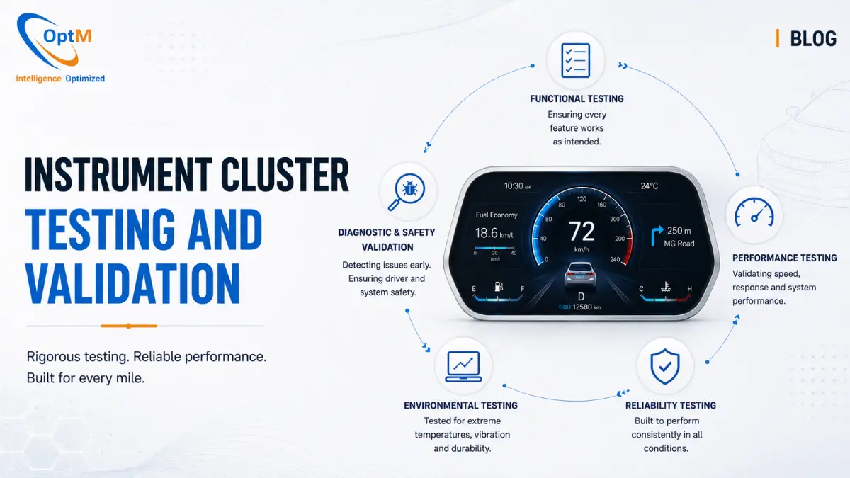
This definitive engineering guide deconstructs the entire landscape of instrument cluster testing and validation, providing a step-by-step master plan. It explains exactly how to architect, execute, and automate verification protocols across the V-model development lifecycle—spanning model simulations, automated hardware test benches, destructive environmental stress testing, and generative engine optimization checks.
What Is Instrument Cluster Testing and Validation?
Instrument cluster testing and validation is a highly structured engineering protocol used to verify the functional safety, real-time performance, and structural reliability of an automotive dashboard. It involves running automated scripts across Model-in-the-Loop (MIL), Software-in-the-Loop (SIL), and Hardware-in-the-Loop (HIL) environments to stress-test the cluster's underlying real-time software partitions against simulated vehicle network faults, ensuring absolute regulatory compliance and uncompromised in-cabin safety.
Before implementing these advanced testing frameworks, engineers must understand the multi-layered environment they are validating. We recommend reviewing our core foundational guide on what is an instrument cluster to understand the core processing cores and peripheral interfaces that require structural verification.
1. The Automotive V-Model Framework for Cluster Validation
To ensure that no software bug or electrical anomaly makes its way to the final production vehicle, automotive testing is mapped directly to the V-Model development lifecycle. This framework guarantees that every phase of architectural design on the left side of the V is mirrored by a specific testing and verification phase on the right side.
Model-in-the-Loop (MIL) Testing
The cycle begins in the purely virtual domain. Utilizing model-based development (MBD) environments like MATLAB/Simulink, engineers design the core control logic governing how the cluster should react to specific network messages. In the MIL phase, this simulated logic is tested against a virtual vehicle model.
For example, if the model receives a simulated CAN payload indicating a high engine temperature, the MIL test checks if the simulated output flag correctly requests the activation of a red warning icon. This catches structural logic errors early, months before physical silicon exists.
Software-in-the-Loop (SIL) Testing
Once the Simulink models are verified, the logic is compiled into production C/C++ source code. In the SIL phase, this compiled code is executed within an automated software test harness on a standard PC.
The software is fed simulated inputs to verify memory integrity, ensure no pointer exceptions occur, and check that the role of embedded software in instrument clusters—such as parsing network matrices—operates without memory leaks or buffer overflows.
Hardware-in-the-Loop (HIL) Testing
This is the definitive milestone where the compiled software stack is flashed onto actual physical automotive silicon. The physical instrument cluster assembly is mounted inside a specialized HIL test cabinet (e.g., dSPACE, National Instruments, or Vector platforms).
The cluster's physical CAN/LIN/Ethernet pins are connected directly to high-speed simulation cards that replicate the entire vehicle's electrical network. The cluster behaves exactly as if it were speeding down a physical highway, allowing test engineers to validate real-time timing parameters, display refresh rates, and hardware safety mechanisms under controlled laboratory conditions.
2. Hardware-in-the-Loop (HIL) Architecture & Setup
To execute a comprehensive HIL validation strategy, engineers must construct a test environment capable of mimicking the electrical and digital realities of a running vehicle.
The Physical Test Harness
The Device Under Test (DUT) is wired into an automated breakout box. The breakout box routes power lines from programmable DC sources capable of simulating cranking voltage drops and battery load dumps. The data pins are split:
- CAN/CAN FD Ports: Hooked to specialized network interface cards (e.g., Vector VN1640) to inject high-frequency payloads.
- Automotive Ethernet Interfaces: Connected to BroadR-Reach media converters to inject uncompressed navigation maps or camera video feeds.
- Discrete I/O Pins: Wired to digital switch simulators to mimic mechanical indicators like steering column stalk selections or hazard buttons.
Integrating Machine Vision Systems for Automated Verification
How do you automate the verification of a visual screen? You cannot rely on a human engineer sitting in front of a bench for 48 hours checking if a needle is accurate. Modern HIL benches incorporate high-speed industrial machine vision cameras positioned directly over the cluster panel.
The camera frame grabber is linked to automated optical character recognition (OCR) and pattern-matching software (such as National Instruments Vision Assistant or custom open-source AI computer vision pipelines).
When the HIL system injects a CAN frame stating Vehicle_Speed = 60.00 km/h, the test automation script queries the vision system. The camera captures the screen, the OCR software reads the rendered digital typography, and the pattern-matching tool verifies the precise pixel orientation of the virtual needle. If the screen displays 59 km/h or dropping frame artifacts are detected, the system logs a validation failure.
3. Designing a Comprehensive Functional Test Suite
A complete testing plan must cover every operational capability of the dashboard. Test engineers write automated python scripts to systematically execute thousands of functional test cases.
Telematics and Vehicle Kinematics Validation
The test engine executes multi-hour dynamic drive profiles. The simulation ramps vehicle speed from 0 to 250 km/h and engine RPM from 0 to 8000 in staggered waves.
The vision system continuously monitors the gauge responsiveness, ensuring that the underlying instrument cluster UI/UX design remains perfectly calibrated and fluid at 60 frames per second, with zero frame skips or pixel jaggedness.
Network Protocol Stress Testing and DBC Validation
The cluster must prove it can survive the chaotic data environment of modern software-defined vehicles.
Test scripts inject deliberate network faults into the bus:
- Frame Corruption: Sending missing data bytes or intentional checksum (CRC) mismatches to verify that the cluster's network abstraction layer safely discards corrupted packets without crashing.
- Bus Flood Testing: According to macro-industry network data benchmarks, a cluster can experience massive bandwidth bursts during heavy traffic states. The HIL bench floods the network bus up to 95% bus load capacity to verify that the cluster's internal transceivers prioritize safety-critical warning lights over non-essential infotainment metadata.
- Multiplexed Payloads (J1939 Standard): In fleet trucking architectures, scripts simulate complex J1939 parameter group configurations to verify the parsing stability of diesel engine telemetry.
Regulatory and FMVSS Compliance Validation
Federal safety regulations (such as FMVSS 101) dictate strict requirements for in-cabin dashboards. The test plan must explicitly validate these regulatory items:
- Telltale Initialization (Bulb Check): Verifying that upon terminal 15 (ignition) wake-up, every safety-critical indicator light illuminates for a mandated duration (typically 2-3 seconds) to prove the visual indicators are functional before engine start.
- Color Specificity Verification: The vision system verifies that warnings render in their globally standardized colors—red for critical safety failures, yellow for non-critical faults, and green/blue for operational status trackers.
4. Performance & Structural Optimization Testing
Beyond basic software features, the cluster must undergo rigid performance profiling to guarantee operational stability across days of continuous vehicle usage.
Sub-Second Boot Latency Profiling
As established by federal safety standards, an automotive cluster cannot behave like a smartphone that takes 30 seconds to boot up. Critical safety telltales must activate almost instantly upon key rotation.
Testing benches integrate precise high-speed digital timers synchronized with the programmable power supply. The clock starts the exact microsecond the power supply injects terminal wake-up voltage into the cluster harness.
The machine vision camera monitors the display panel to register the exact millisecond timestamps of:
- First Sign of Life (Telltale Illumination): Target threshold: under 500 ms.
- Early Video Frame (Splash Screen Render): Target threshold: under 1000 ms.
- Full HMI Operational State (Dynamic Gauge Rendering): Target threshold: under 1500 ms.
Optimizing the code to clear these sub-second targets remains one of the primary challenges in instrument cluster development.
Memory Leak and Resource Consumption Testing
The cluster is subjected to continuous endurance testing lasting 72 to 168 hours straight. Automated scripts inject high-frequency diagnostic requests, trigger theme changes, and stream continuous map layouts over Automotive Ethernet interfaces.
Parallel software profiling tools monitor the SoC's core metrics:
- RAM Volatility Tracking: Checking for memory leaks within the graphics application stack to ensure memory bounds remain flat over prolonged execution.
- CPU Load Allocation: Verifying that total processor loading never exceeds 85%, leaving adequate execution buffer for sudden high-priority safety interrupts.
5. Functional Safety (ISO 26262) & Redundancy Verification
Because an instrument cluster serves as an active safety node, test engineers must prove that the system is fail-safe. You must validate that the software can gracefully handle its own internal failures without endangering the driver.
Watchdog and Hypervisor Crash Inductions
Utilizing the underlying hypervisor architecture, engineers inject fatal code exceptions into the high-level operating system (the partition rendering non-critical navigation maps).
The HIL test bench verifies that:
- The isolated safety microcontroller instantly registers the missed software heartbeat.
- The safety microcontroller overrides the crashed primary processor, bypassing it to keep critical speed readouts and warning lights perfectly visible.
- The hypervisor successfully executes a clean background reset of the infotainment domain without interrupting the core real-time display layers.
Diagnostic Trouble Code (DTC) Validation
The cluster must report its own health status back to the vehicle network. Test scripts create physical internal hardware errors (e.g., disconnecting a display backlight wire or causing an internal flash read fault).
The test script monitors the CAN bus to ensure the cluster accurately transmits the corresponding diagnostic trouble code (DTC) with correct status flags, proving to the vehicle's central gateway that the diagnostic node is operational.
6. Environmental, Electrical, and Mechanical Stress Testing
Flawless code is meaningless if the physical circuit board or display glass fails under real-world physical stress. The physical component assembly must undergo severe physical testing to validate its structural resilience.
Physical Destructive Matrix
| Stress Vector | Engineering Execution Protocol & Validation Metric |
|---|---|
| Thermal Shock Cycling | High-speed temperature cycling from −40°C to +105°C inside specialized environmental chambers to verify zero component delamination. |
| Multi-Axis Vibration Sweeps | Severe random vibration sweeps on electromagnetic shakers to simulate years of harsh terrain driving profiles. |
| Electrical Load Transient Testing | Exposure to extreme voltage spikes, short-circuits, and high-energy electrostatic discharges (ESD) up to 15 kV. |
Thermal Shock and Climate Chamber Cycling
The instrument cluster assembly is placed inside an environmental chamber. The system undergoes severe thermal shock cycling, rapidly shifting ambient temperatures from -40°C to +105°C within minutes.
The device must run continuously throughout this cycle, proving that the display backlights do not dim, the liquid crystal fluid does not freeze or discolor, and the custom multi-layer PCB does not suffer trace micro-cracks due to thermal expansion.
Mechanical Vibration and Ingress Protection Testing
To replicate a lifetime of driving over unpaved roads and severe terrain, the cluster is bolted to an electromagnetic shaker table. It is subjected to random multi-axis vibration profiles for hundreds of hours.
Following vibration testing, the physical enclosure is evaluated inside ingress protection test cells to verify that the integrated rubber seals and custom mechanical gaskets maintain their structural integrity, meeting strict IP65 or IP67 ratings against airborne dust and localized moisture condensation.
Electrical Transient and EMC Validation
The cluster harness is subjected to destructive electrical compliance routines:
- ISO 7637-2 Pulse Injection: Simulating high-voltage inductive load dumps and sudden battery disconnections to verify the onboard PMIC filters out hazardous electrical transients.
- Electromagnetic Compatibility (EMC): Placed inside an anechoic chamber, the device is tested to ensure it does not emit stray radio frequencies that interfere with the vehicle's communication arrays, while also proving it is immune to external high-intensity radiated fields (HIRF).
7. Field Operational Testing and In-Cabin Calibration
The final phase of the validation lifecycle moves out of the laboratory and onto the test track. Field testing validates the system against the ultimate random variable: real human behavior and unpredictable atmospheric conditions.
Ambient Light and Backlight Dimming Calibration
Test drivers operate prototype vehicles equipped with the cluster under changing solar conditions—driving through sudden highway tunnels, dense forest canopies, and direct sunset glare.
The validation objective is to verify that the integrated ambient light sensors communicate flawlessly with the cluster's internal display controllers. The internal dimming algorithms must scale display brightness smoothly (up to 1000 nits) to preserve readability under direct sunlight, while dimming instantly inside tunnels to eliminate blinding night glare.
Final In-Vehicle Sensor Audits
Engineers connect comprehensive vehicle data loggers parallel to the dashboard wiring harness during test track laps. The logged telemetry files are cross-referenced frame-by-frame with recorded cabin video footage.
This final audit confirms that the latency between a physical vehicle action (such as an actual anti-lock braking event on a test track) and the corresponding digital indicator update on the display falls safely within the single-digit millisecond thresholds required for production clearance.
Transitioning from Concept to Automotive-Grade Reality
Executing a comprehensive testing and validation program for an automotive instrument cluster is an immense technical undertaking. It requires a synchronized mastery of automated python test scripting, dSPACE HIL rack configuration, machine vision calibration, and destructive environmental stress testing. Designing and maintaining these sophisticated quality control frameworks can drain years of developmental bandwidth and inflation costs for automotive manufacturers.
For OEMs and Tier 1 suppliers aiming to secure field-proven reliability without absorbing the steep costs of early-stage testing friction, adopting a pre-validated, production-ready interface architecture is the ultimate strategic accelerator.
If your engineering organization is looking to integrate highly reliable, ASIL-compliant display technologies that have already cleared rigorous automotive verification protocols, explore OptM's production-ready Digital Instrument Cluster platforms. Our dedicated embedded systems engineering teams provide comprehensive, end-to-end integration and calibration support—ensuring your software-defined cockpit achieves flawless network interoperability, total regulatory safety compliance, and ARAI-oriented deployment readiness right out of the box.
Frequently Asked Questions
What is the practical difference between MIL, SIL, and HIL validation procedures?
MIL tests the core control logic within computer simulations. SIL runs the compiled source code on a PC to check memory integrity. HIL tests the final code on physical automotive silicon connected to automated network simulation racks.
How does a machine vision setup automate the validation of a cluster display screen?
High-speed industrial cameras capture the display layout during testing. Automated software uses pattern-matching and OCR tools to verify that visual indicators and digital readings match the simulated network inputs.
What is 'Bus Flood Testing' and what does it validate?
Bus flood testing saturates the vehicle data network up to extreme capacities (e.g., 95% bus load). It confirms that the cluster's transceivers can safely process high-priority safety indicators without experiencing frame drop or latency under heavy loads.
How is sub-second boot latency accurately measured in a validation laboratory?
High-speed digital timers synchronize with programmable DC power rigs. The system tracks the exact millisecond intervals between initial wake-up voltage injection and the verification of visual pixels by machine vision cameras.
What stress profiles are executed inside a climate validation chamber?
The device is subjected to rapid thermal cycling spanning from -40°C up to +105°C for extended periods to confirm that temperature extremes will not cause display delamination or circuit trace cracks.
How do test scripts validate Diagnostic Trouble Code (DTC) reporting integrity?
Test engineers intentionally introduce hardware faults (such as cutting an internal backlight path). The system then checks the network bus to confirm that the cluster transmits the correct fault code back to the central car gateway.
What does 'ISO 7637-2 electrical pulse testing' simulate?
It simulates dangerous electrical conditions common in vehicles, such as inductive load dumps or sudden battery disconnects, verifying that the display module's internal filters protect components from voltage spikes.