
Content Writer & SEO Specialist
Content Writer & SEO Specialist
Aditya Sharma is a content writer at OptM Solutions specializing in automotive electronics, embedded systems, telematics, electric vehicle technologies, connected mobility, and autonomous driving technologies.
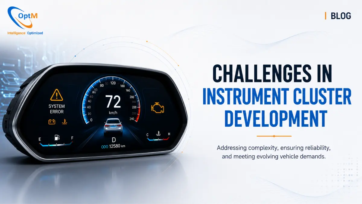
LinkedIn ProfileIn the landscape of modern software-defined vehicles (SDVs), the digital instrument cluster is no longer a passive hardware module with analog components. It has evolved into a highly integrated, deterministic edge-computing hub responsible for safety-critical vehicle diagnostics, Advanced Driver Assistance Systems (ADAS) visualizations, and real-time electric vehicle (EV) telemetry.
For automotive OEMs, Tier 1 suppliers, and embedded hardware and software architects, developing a modern digital cockpit presents an unforgiving matrix of engineering trade-offs. The display must boot in fractions of a second, render heavy 3D graphics seamlessly at 60 frames per second, withstand harsh electrical load dumps, and remain completely secure against remote cybersecurity vulnerabilities—all while operating inside a sealed dashboard cavity with strict Bill of Materials (BOM) cost limits.
This comprehensive engineering guide deconstructs the definitive challenges faced during automotive instrument cluster development and provides production-grade architectural solutions for each engineering bottleneck.
What Is the Core Hurdle in Cluster Development?
The primary challenge in instrument cluster development lies in balancing high-performance, GPU-accelerated graphics rendering with strict, deterministic functional safety constraints. Because a dashboard handles life-saving vehicle alerts, embedded engineers must build multi-layered software stacks and asymmetric hardware architectures that isolate rich consumer applications from safety-critical display logic to guarantee zero system failures.
Before tackling these advanced integration and development bottlenecks, engineers must fully understand the physical components they are managing. Review our comprehensive guide on the core components of instrument cluster systems to contextualize the hardware constraints.
1. Challenge: Meeting Strict Sub-Second Boot Latency Targets
Federal safety regulations (such as FMVSS 101) dictate that safety-critical telltales—such as the oil pressure, braking integrity, and airbag deployment warning lamps—must illuminate almost instantly upon the vehicle's ignition sequence.
The Bottleneck
A modern instrument cluster runs on complex operating systems like Embedded Linux or Android Automotive to drive rich 3D graphics and connectivity. However, unoptimized consumer-grade OS kernels typically take anywhere from 10 to 30 seconds to unpack, initialize memory, mount file systems, and execute application code. This lag creates a severe regulatory non-compliance issue and degrades user experience.
The Architectural Solution
Embedded software teams utilize an intentional multi-stage fast-boot pipeline backed by asymmetric processing cores:
- Early Video & Splash Rendering: The system's primary bootloader initializes an ultra-lightweight hardware abstraction layer (HAL) within the first 300 ms, flashing a static pre-rendered splash screen directly from high-speed NOR flash memory into the display controller frame buffer. This creates an instantaneous visual "sign of life."
- Kernel Stripping and XIP Flash: Engineers aggressively strip out non-essential kernel modules (such as heavy multimedia streaming and USB stacks) from the boot sequence, loading them asynchronously after the primary HMI has launched. Utilizing eXecute-In-Place (XIP) flash allows the core OS kernel to execute code directly from non-volatile memory, bypassing time-consuming RAM copying cycles.
- The MCU Parallel Wakeup: While the heavy application processor (SoC) is booting the primary OS, an independent, low-power safety microcontroller (MCU) boots a deterministic Real-Time Operating System (RTOS) within less than 100 ms, physically taking control of dedicated hardware lines to illuminate the dashboard's LED telltales immediately.
To see a granular, millisecond-by-millisecond breakdown of how this boot workflow is orchestrated, refer to our structural phase blueprint on how instrument cluster works.
2. Challenge: Thermal Management in Sealed Dashboard Cavities
As display panels grow larger and user interfaces transition into rich 3D environments, the underlying processors must work significantly harder, generating vast amounts of thermal energy.
The Bottleneck
Unlike desktop computers or server architectures, an automotive cockpit display node is trapped inside a tightly confined, completely unventilated dashboard cavity. Incorporating mechanical cooling fans is strictly prohibited because they introduce noise, pull in fine ambient dust particles, and represent a high-risk mechanical moving part prone to catastrophic failure.
The Architectural Solution
Thermal engineering teams must design highly sophisticated passive heat dissipation frameworks:
- Heavy Aluminum Die-Cast Housing: The cluster's physical enclosure is engineered to serve as an active heat sink. High-conductivity thermal interface materials (TIM), such as specialized silpad gap fillers, bridge the physical gap between the high-performance SoC die and the inner aluminum chassis wall, wicking thermal energy directly away from the silicon.
- Thermal Via Matrix Layouts: The multi-layer custom PCB incorporates hundreds of structural thermal vias positioned directly underneath the power management IC (PMIC) and processor pads. These copper-lined paths pull vertical heat away from the sensitive component layers, distributing the thermal profile evenly across the wide grounding planes of the board.
- Software Dynamic Voltage Scaling (DVFS): Embedded software daemons actively monitor on-chip silicon thermal diodes. If temperatures approach maximum operational thresholds (typically +85°C to +105°C), the software dynamically steps down the processor clock frequency or slightly reduces the display backlight luminance to stabilize thermal profiles without dropping frames.
3. Challenge: Preventing System Freezes and Memory Corruption
Because a digital dashboard is software-defined, it faces a risk that legacy analog pointer needles never encountered: software application crashes, kernel panics, or memory leaks.
The Bottleneck
If a vehicle's dashboard screen completely freezes while cruising down a highway, the driver is blinded to their current velocity, active ADAS lane boundary markers, and immediate braking system updates. If a memory leak within a non-critical component (such as an audio track playlist asset) causes the entire system to run out of volatile memory, it can bring down the safety-critical rendering layers alongside it.
The Architectural Solution
To achieve strict ISO 26262 Automotive Safety Integrity Level (ASIL) compliance, engineers deploy Type 1 Bare-Metal Hypervisors to physically fence off processing tasks:
| Bare-Metal Type 1 Hypervisor | Virtual Machine 1 (Safety-Critical) | Virtual Machine 2 (Non-Safety-Critical) |
|---|---|---|
| OS Layer | Deterministic RTOS Environment | High-Level Operating System (Linux/Android) |
| Responsibilities | Speedometer & Fuel Metrics, ASIL-Rated Alert Telltales | 3D Navigation Mapping, Media & Comfort Interfaces |
- Strict Memory Sandboxing: The bare-metal hypervisor divides the System-on-Chip (SoC) resources into isolated virtual machines. The non-critical infotainment domain runs on Linux or Android, while the safety-critical cluster domain runs on a deterministic RTOS (such as QNX). The hypervisor implements absolute memory protection; if the Linux domain suffers a kernel panic, the RTOS partition continues executing with zero interruption.
- Hardware Watchdog Heartbeats: The safety microcontroller (MCU) operates a background loop that demands a recurring digital "heartbeat" signal from the main SoC's graphics application pipeline. If the SoC's graphics system locks up, it misses a heartbeat window. The MCU immediately detects the failure, triggers an isolated hard reset of the SoC, and instantly routes raw CAN network packets to an independent, basic hardware display plane to keep critical metrics visible during the 1-second system reboot window.
To study the specific memory map allocations and inter-process communication (IPC) frameworks that prevent code corruption, view our in-depth post on instrument cluster architecture.
4. Challenge: Mitigating Cybersecurity Exploits and Network Spoofing
Modern instrument clusters are no longer isolated digital islands. They feature advanced wireless configurations, integrate with cloud ecosystems for asset management, and frequently ingest over-the-air (OTA) firmware packages.
The Bottleneck
Every external network connection introduces a potential attack surface for malicious cyber actors. If a hacker compromises the infotainment gateway, they could potentially cross over into the cluster's software layer to spoof speed readouts, mute critical safety warnings, or broadcast malicious frames back into the core powertrain CAN network.
The Architectural Solution
Automotive security engineers deploy a zero-trust multi-layered defensive security topology:
- Hardware Security Modules (HSM): High-grade cluster SoCs incorporate a dedicated HSM directly on the silicon die. The HSM features an isolated cryptographic processor that operates its own secure boot sequence. It stores all master cryptographic keys and vehicle certificates in fenced-off registers that are physically inaccessible to the primary operating system.
- Cryptographic Secure Boot Keys: Every phase of the boot sequence is verified using public-key cryptography. The HSM verifies the digital signature of the secondary bootloader, which in turn verifies the signature of the OS kernel, which then verifies the signature of the HMI application layout. If a single bit of code has been altered or tampered with, the boot pipeline is halted.
- Secure CAN Message Authentication (SecOC): When the cluster interacts with distributed ECUs, the embedded network stack utilizes Secure Onboard Communication (SecOC) protocols. Every critical data payload is appended with a cryptographic Message Authentication Code (MAC) and a freshness counter, preventing hackers from executing replay attacks or injecting spoofed network telemetry.
5. Challenge: Balancing Bandwidth and Signal Prioritization
As advanced sensor networks (Radar, LiDAR, high-definition optical arrays) become standard, the cluster is bombarded with a massive influx of environmental and kinematic telemetry frames.
The Bottleneck
If a cluster is attempting to digest data from 100 different ECUs simultaneously, it can suffer from network bus collisions, buffer saturation, and high latency. If an active ADAS forward-collision warning packet arrives at the cluster transceiver at the exact microsecond that the media layer is loading a heavy song asset, the network cannot afford to experience data delivery delays.
The Architectural Solution
Engineers manage this high-throughput environment by executing strict instrument cluster integration with ECUs, sensors and vehicle networks protocols:
- Deterministic CAN Arbitration: Data frames are mapped to strict numerical identification metrics. Lower identifier codes grant the packet dominant arbitration priority on the physical two-wire bus. Airbag, braking, and steering alerts are assigned top-tier priority identifiers, allowing them to instantly clear the wire ahead of non-critical comfort telemetry.
- Automotive Ethernet Migration: To handle data-dense features like real-time surround-view camera feeds and high-resolution map tiles without saturating the CAN bus, engineers deploy 100BASE-T1 or 1000BASE-T1 Automotive Ethernet pipelines. This provides dedicated gigabit throughput over lightweight unshielded twisted pair wires.
- Hardware Acceptance Filtering: The cluster's internal CAN controllers are configured with aggressive hardware-level message filters. Rather than passing every single frame up to the CPU for software analysis, the silicon controller instantly discards any network identifier packet that is not explicitly required by the dashboard display logic, drastically reducing processor load.
6. Challenge: Designing a Fluid HMI under Strict Hardware Limits
Automotive procurement leads operate under unforgiving Bill of Materials (BOM) cost boundaries. Every fraction of a dollar saved on a chip choice translates into millions of dollars in net profit over a vehicle's manufacturing lifecycle.
The Bottleneck
Embedded developers are routinely forced to design fluid, interactive user interfaces that run on highly cost-optimized, low-frequency processors with restricted memory footprints. Yet, the consumer demands a premium experience that matches the fluid responsiveness of modern smartphones. If a digital gauge needle stutters or drops frames, it creates an impression of poor vehicle quality and increases driver visual fatigue.
The Architectural Solution
Developing high-performing layouts requires highly specialized instrument cluster UI/UX design strategies and deeply optimized software tools:
- Vector-Based Qt/QML Engines: Instead of utilizing heavy, static pre-rendered bitmap images for every angle of a needle rotation, engineers rely heavily on the cross-platform Qt framework. Qt compiles interface modules directly down to clean, highly efficient native C++ code structures, allowing complex elements to be drawn dynamically using vector mathematics.
- GPU Hardware Acceleration: The Qt graphic rendering pipeline issues draw calls directly to the SoC's onboard GPU via OpenGL ES or Vulkan APIs. This offloads the entire pixel rasterization process away from the primary CPU, allowing the dashboard to maintain a fluid, anti-aliased 60 frames per second (fps) refresh rate without exhausting the central processing budget.
- Texture Atlas Packing: Graphical components are packed into uniform, single-image texture atlases during compilation. This minimizes the total number of texture binding switches required by the GPU during execution, maximizing rendering throughput and dropping memory access latencies.
7. Challenge: Passing Rigorous Quality and Compliance Validations
Before an automotive cluster can receive road-going clearance or production sign-off, it must prove it can survive a literal lifetime of physical abuse and environmental extremes.
The Bottleneck
A cluster must clear intensive quality checks including ARAI readiness, thermal shock drops, severe mechanical multi-axis vibrations, and high-voltage electrostatic dumps. Designing an architecture that passes these checks on the first attempt is incredibly difficult, and failing validation cycles mid-way through a development timeline can set a product launch back by twelve to eighteen months.
The Architectural Solution
Engineering networks implement a rigorous, automated verification matrix from day one of the development lifecycle:
- Hardware-in-the-Loop (HIL) Test Automation: Physical prototypes are locked inside high-speed HIL test benches (such as dSPACE or Vector systems). Automated python scripts bombard the hardware transceivers with millions of corrupted frames, intentional electrical transient drops, and falsified data signals to verify the robustness of the system's software filters.
- High-Speed Machine Vision Audits: Automated industrial cameras mounted over the HIL benches execute high-resolution optical character recognition (OCR) and structural pattern matching. This automated eye tracks rendering latency, verifies warning icon chromatic specificity, and logs whether any micro-stuttering occurs within the visual outputs.
To review a step-by-step structural operational blueprint for configuring these automated test suites, explore our comprehensive handbook on instrument cluster testing and validation.
Accelerating Production-Grade Cockpit Architectures
Overcoming the interconnected development challenges of modern digital instrument clusters—from achieving sub-second boot times and passive thermal dissipation to managing Type-1 hypervisor segregation and GPU-accelerated Qt layouts—requires significant engineering bandwidth and highly specialized automotive expertise. Attempting to build and validate these safety-critical platforms completely from scratch can easily exhaust development timelines and expand engineering budgets.
For Tier 1 suppliers and automotive OEMs aiming to eliminate design friction and secure market-ready field performance, bypassing early-stage prototyping loops by leveraging a pre-validated architectural platform is the ultimate strategic accelerator.
If your organization is seeking to deploy scalable, ASIL-compliant display topologies into your next generation of software-defined vehicles, explore OptM's production-ready Digital Instrument Cluster platforms. Our dedicated embedded systems engineering teams provide comprehensive, end-to-end integration support—spanning custom CAN/J1939 network configuration, low-level device driver development, secure boot provisioning, and optimized Qt HMI development—ensuring your vehicle's primary cockpit interface delivers uncompromised safety, visual fluidity, and production readiness.
Frequently Asked Questions
Why is thermal management inside a dashboard cavity more complex than in consumer electronics?
Dashboard spaces are sealed, unventilated cavities. To prevent dust ingress and noise issues, engineers cannot use active cooling fans, forcing them to rely entirely on passive aluminum heat sinks and strategic PCB layouts.
How do embedded teams resolve conflicting processing requirements between graphics and safety?
They implement bare-metal Type 1 hypervisors to split the processor. Non-safety components are isolated to a high-level OS like Linux, while safety-critical data paths run on a deterministic RTOS.
What strategy eliminates the visual lag of a virtual gauge needle on a low-spec SoC?
Engineers leverage frameworks like Qt to build vector-based graphics compiled to native C++. This allows direct hardware acceleration on the GPU, offloading the task from the CPU to maintain 60fps.
How does secure boot logic prevent remote hacking exploits over OTA pathways?
A Hardware Security Module (HSM) uses cryptographic keys to verify the digital signature of each software layer during boot. If any unauthorized changes are detected in the file system, the HSM halts execution.
How do engineers overcome the strict data limits of standard CAN buses when designing high-res UIs?
Engineers transition data-heavy video and mapping assets to high-speed Automotive Ethernet backbones, leaving the standard CAN bus to handle small, high-priority numerical sensor updates.
What is a 'watchdog heartbeat timeout error' and how is it resolved?
This happens if the primary graphics engine locks up and fails to send its periodic check-in signal to the safety MCU. The MCU quickly detects the timeout, forces an isolated reboot of the main processor, and takes direct control of the display layer to preserve critical indicators.
How do texture packing strategies optimize limited volatile memory spaces?
Graphic designers consolidate individual icon and element images into unified layout sheets during software compilation. This minimizes texture-binding changes on the GPU, lowering memory access latencies and processing overhead.