
Content Writer & SEO Specialist
Content Writer & SEO Specialist
Aditya Sharma is a content writer at OptM Solutions specializing in automotive electronics, embedded systems, telematics, electric vehicle technologies, connected mobility, and autonomous driving technologies.
LinkedIn ProfileIn production-grade automotive environments, the days of bolting a discrete radio receiver and a simple LCD screen into a plastic dashboard housing are completely over. Today’s software-defined vehicles (SDVs) demand centralized, high-performance computing platforms that orchestrate everything from 3D navigation and cloud telematics to safety-critical Advanced Driver Assistance Systems (ADAS). To achieve this, original equipment manufacturers (OEMs) and Tier-1 suppliers must source, integrate, and validate an incredibly complex bill of materials (BOM).
Understanding the individual hardware and software elements that make up this BOM is non-negotiable for modern engineering and procurement leaders. According to a recent industry analysis by MarketsandMarkets, the global automotive infotainment market is scaling rapidly, driven by the intense demand for intelligent in-cabin experiences and the widespread adoption of electric vehicle (EV) architectures. But to capitalize on this growth, teams must move beyond high-level feature lists and dissect the microscopic realities of the hardware.
If you are exploring the foundational concepts of this technology, we highly recommend starting with our definitive pillar guide on What Is Infotainment System architectures. However, in this comprehensive guide, we are looking under the glass. We will break down every critical piece of silicon, networking interface, display hardware, and software abstraction layer that constitutes the modern digital cockpit, revealing exactly how these elements interact to deliver zero-latency performance under extreme environmental conditions.
What Are the Components of an Infotainment System?
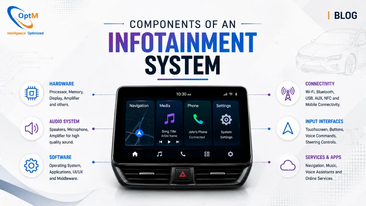
The components of an infotainment system comprise a heterogeneous System-on-Chip (SoC) for centralized processing, high-bandwidth volatile memory (LPDDR4/5), Universal Flash Storage (UFS) for non-volatile data, and automotive-grade touch display panels. These core hardware elements are supported by specialized connectivity modules (LTE/5G, BLE), audio Digital Signal Processors (DSPs), and complex in-vehicle networking transceivers (CAN FD, Automotive Ethernet), all governed by a Type-1 Hypervisor and Real-Time Operating Systems (RTOS).
To understand how these parts communicate to create a seamless user experience, engineering teams must deeply understand How Does Infotainment System Work at the data-pipeline level.
1. The Computing Core: The Heterogeneous System-on-Chip (SoC)
At the heart of the digital cockpit sits the System-on-Chip (SoC). In the past, vehicles utilized dozens of decentralized Electronic Control Units (ECUs) to manage individual features. Today, domain controller architectures consolidate these workloads onto a single, massively powerful piece of automotive-grade silicon.
Unlike a smartphone processor, an automotive SoC must endure brutal thermal cycles (-40°C to +85°C ambient), intense vibration, and electromagnetic interference, all while guaranteeing deterministic, fail-safe execution. To handle this, the SoC features a heterogeneous architecture, dividing its silicon into specialized processing zones.
Multi-Core Application Processors (CPU)
The central processing unit is typically built on a 64-bit ARM Cortex-A architecture (such as Cortex-A76 or Cortex-A78 cores). These high-performance cores are tasked with running the heavy, unsecure domain software—such as Android Automotive OS (AAOS), media decoders, browser engines, and high-level navigation logic.
Real-Time Microcontrollers (MCU / Safety Cores)
Sitting on the same silicon die, but logically and physically isolated, are the safety cores (such as ARM Cortex-R or Cortex-M). These cores operate within the secure domain. They are engineered for hard real-time execution, ensuring that critical Functions of Infotainment System—such as rendering ABS warning lights or processing CAN bus interrupt signals—are executed within strict microsecond deadlines, entirely unaffected by the workload of the main application processors.
The Graphics Processing Unit (GPU)
The GPU handles the massive mathematical workload of rendering complex user interfaces and 3D navigation environments. In an automotive context, the GPU must support hardware virtualization. This allows the hypervisor to slice the GPU's rendering pipelines, enabling it to drive the central infotainment screen and the driver's digital instrument cluster simultaneously, while ensuring that a graphics crash on the media screen cannot freeze the speedometer rendering.
Neural Processing Units (NPU) and AI Accelerators
As in-cabin intelligence evolves, modern SoCs integrate dedicated Neural Processing Units. The NPU accelerates edge-AI workloads, such as natural language processing (NLP) for voice commands without cloud connectivity, or computer vision inferencing for integrated Driver Monitoring Systems (DMS). By processing these matrix multiplications on dedicated silicon rather than the CPU, the system dramatically reduces thermal output and latency.
The Hardware Security Module (HSM)
With connected vehicles facing escalating cyber threats, the SoC must include a physically isolated Hardware Security Module. The HSM features its own secure processor, random number generators, and cryptographic accelerators. It acts as the ultimate root of trust, validating secure boot sequences and managing the encryption keys required for secure Over-The-Air (OTA) updates.
2. Memory Architectures: Volatile and Non-Volatile Storage
A high-performance SoC is useless if it is starved for data. The memory infrastructure of an infotainment system must balance massive bandwidth requirements with the extreme endurance mandates of the automotive lifecycle.
Volatile Memory (RAM): LPDDR4 and LPDDR5
To feed the GPU with high-resolution textures and allow the CPU to juggle multiple operating systems via a hypervisor, the system relies on Low-Power Double Data Rate (LPDDR) synchronous dynamic RAM. Modern digital cockpits utilize LPDDR4x or LPDDR5 modules.
From an OEM integration perspective, RAM bandwidth is the primary bottleneck for multi-display setups. If the system is rendering a 4K center display and a 1080p instrument cluster simultaneously, the memory bus must sustain tens of gigabytes per second of throughput. Furthermore, this memory must feature in-line Error Correcting Code (ECC) to detect and correct single-bit flips caused by cosmic radiation or electromagnetic interference, preventing fatal kernel panics.
Non-Volatile Storage: UFS (Universal Flash Storage)
Legacy systems relied on eMMC (embedded Multi-Media Controller) storage, which utilized a half-duplex parallel interface. Modern domain controllers have migrated exclusively to UFS (Universal Flash Storage) 3.1 or 4.0 standards.
UFS utilizes a full-duplex serial interface with differential signaling, allowing the system to read and write data simultaneously. It supports native Command Queuing (NCQ), which is critical for an automotive environment. For example, the system can rapidly write gigabytes of OTA firmware updates to a hidden storage partition while simultaneously streaming high-bitrate map data to the navigation app, without causing the user interface to stutter. The selection of high-endurance UFS chips is a fundamental consideration when engineering the broader Infotainment System Architecture.
3. The Visual Layer: Automotive-Grade Displays and HMI
The display panel is the primary physical interface between the vehicle and the user. Designing and sourcing these components requires navigating severe optical, thermal, and mechanical constraints.
Liquid Crystal Displays (LCD) and OLEDs
While consumer tablets use standard IPS LCDs or OLEDs, automotive displays are heavily modified. They must survive the "greenhouse effect" of a parked car, where dashboard surface temperatures can exceed 90°C.
-
TFT-LCD: Thin-Film Transistor LCDs are the industry standard, offering high brightness and long lifespans. They require powerful LED backlighting arrays that generate significant heat, requiring careful thermal management.
-
OLED: Organic Light Emitting Diodes are increasingly adopted in premium B2B applications for their infinite contrast ratios and ability to bend around curved dashboard contours. However, engineering teams must deploy aggressive software pixel-shifting algorithms to prevent "burn-in" of static UI elements like the clock or climate controls over a 10-year vehicle lifespan.
Touch Panels and Optical Bonding
To capture user inputs, a capacitive touch sensor grid is integrated into the display. In a production-grade system, the gap between the cover glass, the touch sensor, and the display matrix is eliminated using a process called Optical Clear Adhesive (OCA) bonding. This removes the air gap, preventing internal condensation, eliminating internal light reflection, and significantly increasing the display's structural resistance to physical impacts and vibration.
UI/UX Aesthetics and Brand Identity
The physical screen is brought to life by the Human-Machine Interface (HMI) software, often built using tools like the Qt Framework. Mastering Infotainment System UI/UX Design requires a deep commitment to cognitive load reduction.
In premium, B2B-focused SDV deployments, UI engineers strictly avoid cluttered, overly "futuristic" sci-fi interfaces that distract the driver. Instead, the design language is rooted in executive minimalism. Layouts prioritize rapid glanceability, utilizing dark mode matrices (such as a deep #001941 background) contrasted sharply with vibrant, brand-aligned active states (like #0278A0 primary accents and #C2FB81 success/charging indicators). This precise control over color palettes ensures the display remains legible under direct sunlight while projecting a high-end luxury aesthetic.
Display Serialization: FPD-Link III and GMSL
Because the central SoC is often located deep within the dashboard or under a seat to manage thermal output, the uncompressed video data must travel over cables to the display panel. Standard HDMI cables cannot survive the electromagnetic noise of a vehicle. Instead, engineers use Gigabit Multimedia Serial Link (GMSL) or FPD-Link III serializers/deserializers (SerDes). These chips convert the massive parallel video data from the SoC into a high-speed serial stream that travels over a single, heavily shielded coaxial or twisted-pair cable, delivering flawless video to the screen up to 15 meters away.
4. Connectivity and Telematics Modules
An infotainment system isolated from the cloud is functionally obsolete. The integration of high-bandwidth wireless connectivity represents the foundation of the connected vehicle ecosystem.
The Network Access Device (NAD) and Telematics Control Unit (TCU)
Cellular connectivity is handled by the NAD, which is often integrated into a broader Telematics Control Unit (TCU). The TCU houses the LTE or 5G modems, SIM/eSIM architectures, and RF front-end components.
From a Tier-1 implementation workflow, the TCU acts as the vehicle's secure gateway to the internet. It enables real-time traffic updates, cloud-based voice recognition, and media streaming. More importantly, it facilitates the MQTT or WebSockets telematics pipelines that send encrypted diagnostic data back to the OEM's enterprise cloud for predictive maintenance analysis.
Wi-Fi and Bluetooth Low Energy (BLE)
Dual-band Wi-Fi (802.11ac/ax) chips are integrated to allow the vehicle to act as a mobile hotspot, and to connect to home networks for massive OTA data downloads while parked. Bluetooth and BLE modules handle hands-free calling, wireless Apple CarPlay/Android Auto projection, and digital key integrations, allowing a driver's smartphone to securely unlock and start the vehicle via localized cryptographic handshakes.
Global Navigation Satellite System (GNSS)
Precision location data is captured by multi-constellation GNSS modules (supporting GPS, Galileo, GLONASS, and BeiDou). For advanced ADAS and EV routing, standard GPS is insufficient. Modern modules utilize Automotive Dead Reckoning (ADR), combining satellite data with the vehicle's internal wheel-speed sensors and a 6-axis Inertial Measurement Unit (IMU). This ensures that even when the vehicle is deep inside a concrete parking garage with zero satellite visibility, the infotainment system renders the vehicle's position on the map flawlessly.
5. The Audio Domain: DSPs and Amplifiers
The acoustic experience within a vehicle is managed by a highly specialized set of hardware components dedicated entirely to audio processing and routing.
The Audio Digital Signal Processor (DSP)
The SoC offloads the heavy lifting of audio equalization to a dedicated DSP. The DSP handles complex audio routing matrices—ensuring that a phone call routes only to the driver's headrest speaker, while the kids in the back continue to hear the movie audio.
Crucially, the DSP manages Active Noise Cancellation (ANC). By utilizing microphones distributed throughout the cabin to monitor low-frequency engine drone and tire noise, the DSP generates inverted sound waves and plays them through the cabin speakers in real-time, effectively cancelling the ambient noise and creating a silent, premium cabin environment.
The A2B Bus (Automotive Audio Bus)
Historically, routing audio to dozens of speakers required massive, heavy bundles of analog copper wire. Modern architectures leverage the A2B bus developed by Analog Devices. A2B daisy-chains multiple microphones, amplifiers, and speakers together using a single unshielded twisted pair (UTP) wire. This drastically reduces the weight of the vehicle's wiring harness while delivering high-fidelity digital audio with near-zero latency.
6. In-Vehicle Networking: The Physical Interfaces
To function as a centralized domain controller, the system must interface with the rest of the vehicle. This requires a suite of networking transceivers and controllers soldered directly onto the system's printed circuit board.
CAN FD Transceivers
For communicating with legacy ECUs, body control modules, and powertrain controllers, the board features Controller Area Network Flexible Data-Rate (CAN FD) transceivers. These chips convert the digital logic of the SoC into the differential voltage levels required to push data across the vehicle's copper wiring harness, allowing the screen to display real-time RPM, tire pressure, and battery state-of-charge.
Automotive Ethernet PHYs and Switches
For high-bandwidth communication—such as pulling raw, uncompressed video feeds from 360-degree ADAS cameras or routing data to rear-seat displays—the system utilizes Automotive Ethernet (IEEE 802.3bw 100BASE-T1 or 1000BASE-T1). The board incorporates specialized Ethernet PHY (Physical Layer) chips and internal routing switches. Unlike standard IT ethernet, Automotive Ethernet utilizes a single twisted pair of wires to reduce weight and implements Time-Sensitive Networking (TSN) standards to guarantee that critical camera data is never delayed by lower-priority media traffic.
The complexity of bridging these varied networks is exactly why Infotainment System Integration with ECUs, Sensors, Displays and Connectivity Modules is considered one of the most difficult engineering disciplines in modern vehicle design.
7. The Physical Infrastructure: PCBs and Thermal Management
The unsung heroes of the digital cockpit are the physical structures that hold the silicon together and prevent it from melting under heavy computational loads.
High-Density Interconnect (HDI) PCBs
The printed circuit board (PCB) of a modern infotainment unit is a marvel of microscopic engineering. Because the SoCs and LPDDR memory chips possess hundreds of tiny solder bumps (BGA packaging), the PCB must use High-Density Interconnect (HDI) manufacturing. These boards feature up to 12 layers of copper, utilizing micro-vias drilled by lasers to route high-speed digital signals without cross-talk or impedance mismatches. The PCB substrate (often High-Tg FR4) is specifically selected to withstand the thermal expansion and contraction of an automotive environment without cracking the delicate solder joints.
Passive Thermal Management Solutions
A high-performance SoC rendering 3D graphics and compiling OTA updates generates massive amounts of heat. Because mechanical cooling fans are prone to failure due to dust and vibration over a 10-year lifespan, engineers rely heavily on passive thermal management.
The SoC is bonded to massive, custom-machined aluminum heat sinks using high-performance thermal interface materials (TIM). The heat is wicked away from the silicon and dissipated into the ambient air behind the dashboard. Navigating these strict thermal envelopes—balancing the demand for higher processing power against the physical limits of passive cooling—remains one of the core Challenges in Infotainment System Development.
8. Software Components: The Invisible Infrastructure
Hardware is merely potential; software is the execution. The software stack of an infotainment system is as complex and heavily engineered as the physical silicon.
The Type-1 Hypervisor
As discussed, the Type-1 Hypervisor (like QNX Hypervisor) sits directly on the bare metal of the SoC. It abstracts the physical CPU cores, RAM, and GPU pipelines, slicing them into secure, isolated virtual machines. This software component is the foundational bedrock of system safety, ensuring that the crashing of a consumer app can never bring down the vehicle's critical instrument displays.
Real-Time Operating Systems (RTOS) and AAOS
Inside the hypervisor's virtual machines run the actual operating systems. The secure domain runs an RTOS (like QNX Neutrino), which guarantees deterministic execution of CAN network routing and safety graphics. The unsecure domain runs complex, feature-rich OS environments like Android Automotive OS (AAOS) or custom Yocto-based Embedded Linux distributions.
Understanding the interaction between these kernels is vital, which is why engineering teams invest heavily in analyzing the Role of Embedded Software in Infotainment System stability and architecture.
The Vehicle Hardware Abstraction Layer (VHAL)
The VHAL is the critical software bridge. It translates the high-level API calls from applications (e.g., "turn on the AC") into the specific, low-level binary CAN payloads required by the specific vehicle model. This abstraction allows OEMs to use the same Android codebase across completely different vehicle platforms by simply rewriting the VHAL layer.
9. Real-World Workflow: How Components Collaborate During an OTA Update
To truly understand how these components operate as a unified ecosystem, let's look at a critical, real-world deployment scenario: An OEM pushing a critical over-the-air (OTA) firmware update to improve the EV regenerative braking algorithm.
-
The Connectivity Ingress: The TCU's 5G Modem receives the encrypted OTA notification from the OEM cloud.
-
Storage and Queuing: The incoming binary file is routed through the SoC, bypassing the CPU via Direct Memory Access (DMA), and written directly into a background partition of the UFS 3.1 Non-Volatile Memory.
-
Cryptographic Validation: The Hardware Security Module (HSM) reads the downloaded package, executing rapid RSA hash calculations to verify the OEM's cryptographic signature, ensuring the file has not been intercepted or tampered with by malicious actors.
-
Network Translation: The Type-1 Hypervisor allocates processing time for the Embedded Linux Middleware to unpack the payload. The VHAL translates the firmware update into specific diagnostic programming protocols (like UDS over CAN).
-
Physical Distribution: The CAN FD Transceiver broadcasts the new firmware data across the vehicle's copper wiring harness to the target Powertrain ECU.
-
Visual Confirmation: Simultaneously, the GPU executes fragment shaders via the Qt Scene Graph, updating the OCA-bonded LCD Display to show the driver a perfectly rendered, #C2FB81-colored progress bar indicating that the vehicle's software enhancement is successfully underway.
This flawless execution is not magic. It is the result of thousands of hours of Infotainment System Testing and Validation, ensuring that every physical chip and line of code works in perfect, deterministic harmony.
Final Thoughts: Sourcing the Future of the SDV
The components of an infotainment system represent the most complex convergence of consumer electronics, high-performance computing, and heavy-duty industrial engineering on the planet. For procurement teams, system architects, and OEM leaders, selecting the right mix of silicon, memory, networking transceivers, and embedded software is the critical difference between launching a market-leading digital cockpit and facing devastating software recalls.
As the industry pivots entirely toward software-defined mobility, building a reliable domain controller requires partnering with engineering teams who understand both the microscopic silicon realities and the macro-level software architectures.
For Tier-1 suppliers and OEMs looking to integrate high-performance, functionally safe, and brilliantly designed in-cabin computing platforms, explore the comprehensive engineering capabilities of the Automotive Infotainment System engineered by OptM Solutions.
Frequently Asked Questions (FAQs)
Why is UFS preferred over eMMC for modern infotainment storage?
UFS (Universal Flash Storage) utilizes a full-duplex serial interface with Command Queuing (NCQ), allowing the system to read map data and write OTA updates simultaneously. eMMC is half-duplex and bottlenecks under heavy concurrent read/write loads.
What is the difference between an application core and a safety core in an automotive SoC?
Application cores (e.g., ARM Cortex-A) are designed for maximum data throughput and run complex OSs like Linux. Safety cores (e.g., ARM Cortex-R) are lockstep microcontrollers designed for hard real-time determinism and strict functional safety execution.
How do engineers prevent OLED burn-in on automotive displays?
Engineers implement aggressive software pixel-shifting algorithms that microscopically move static elements (like the digital clock or climate icons) every few minutes, alongside dynamic dimming protocols based on ambient light sensors.
Why do infotainment displays require optical bonding?
Optical Clear Adhesive (OCA) bonding removes the air gap between the cover glass and the LCD/OLED panel. This prevents internal condensation, eliminates glare from internal light reflection, and massively increases structural resistance to vibration and impact.
How does the A2B bus reduce wiring weight for audio components?
The Automotive Audio Bus (A2B) replaces heavy, multi-wire analog audio bundles by daisy-chaining microphones, amplifiers, and speakers together using a single unshielded twisted pair (UTP) wire, transmitting high-fidelity digital audio bidirectionally.
What thermal management solutions are used for high-performance SoCs?
Because mechanical fans fail in automotive environments, systems rely on passive cooling. This involves High-Density Interconnect (HDI) PCBs, high-performance Thermal Interface Materials (TIM), and massive custom-machined aluminum heat sinks to wick heat away from the silicon.
What is the function of the FPD-Link III or GMSL chips?
They are Serializer/Deserializer (SerDes) chips. They convert the massive parallel video data from the GPU into a high-speed serial stream that can travel over long, heavily shielded coaxial cables to remote display panels without electromagnetic interference.