
Content Writer & SEO Specialist
Content Writer & SEO Specialist
Aditya Sharma is a content writer at OptM Solutions specializing in automotive electronics, embedded systems, telematics, electric vehicle technologies, connected mobility, and autonomous driving technologies.
LinkedIn ProfileImagine sitting in the driver's seat of a next-generation electric vehicle. You tap the sleek, minimalist central display to lower the cabin temperature. Instantly, the air conditioning kicks in, the screen updates the climate UI seamlessly at 60 frames per second, and your Spotify playlist continues playing without a single skipped beat.
To the driver, this feels like magic.
But to an embedded systems engineer, that single tap initiates a violent, microsecond-perfect explosion of computational activity. In the blink of an eye, a capacitive touch signal is digitized, routed through a virtualized operating system, translated by middleware into automotive network protocols, securely transmitted across high-speed copper wires, executed by a remote electronic control unit (ECU), and validated back to the main display.
If you are an OEM, a Tier-1 supplier, or an engineering leader looking to build scalable software-defined vehicles (SDVs), understanding this invisible workflow is no longer optional. It is the baseline for survival in the modern mobility market.
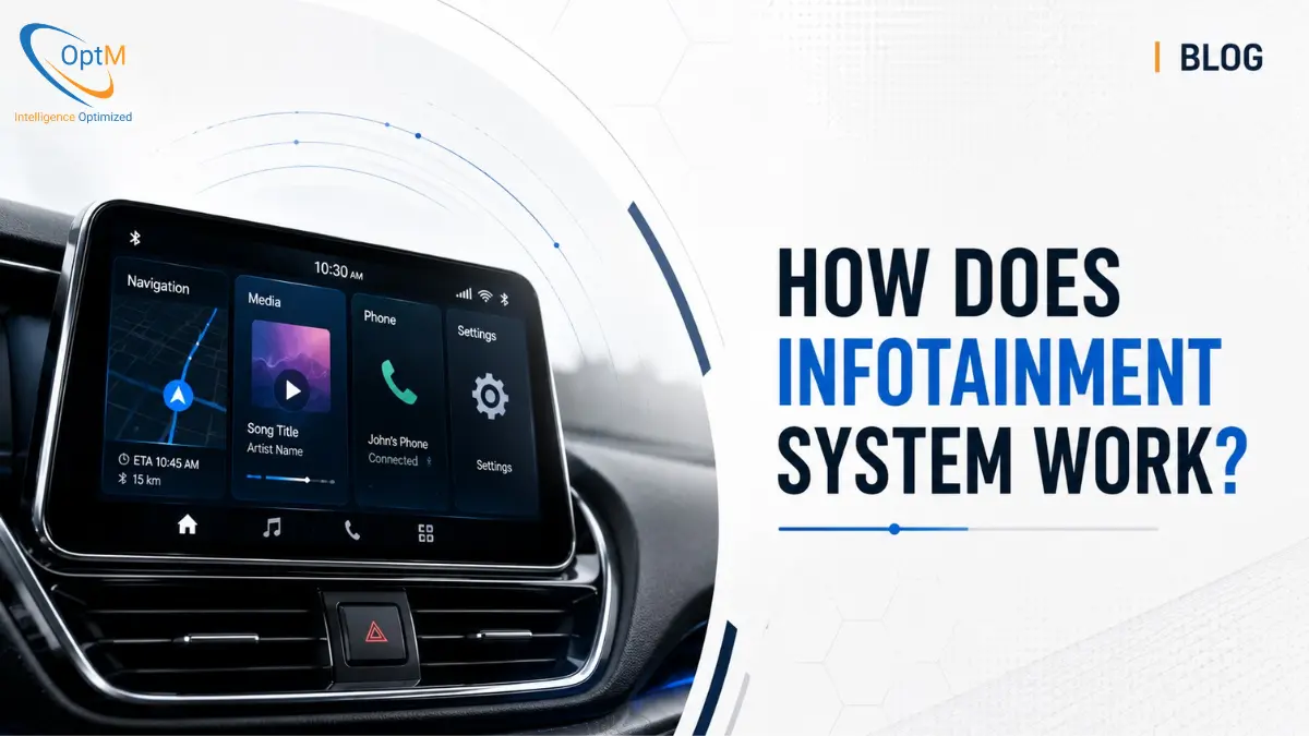
Today, we are moving past surface-level definitions. We are going to break down exactly How Does Infotainment System Work at the microscopic, silicon-and-code level, mapping the entire journey of data from the human touch down to the vehicle's powertrain.
The Core Definition: What is Actually Happening?
Before we dive into the micro-mechanics, let’s establish a clear baseline of what we are dealing with.
What is an Infotainment System at the computational level? An automotive infotainment system operates through a highly integrated, multi-layered software and hardware architecture. It captures analog inputs (via touch or voice), digitizes them through a digital signal processor (DSP), and routes the data through an operating system's middleware. The system then translates these commands into vehicular protocols (like CAN FD or Automotive Ethernet), allowing the central computing unit to exchange real-time telemetry with peripheral ECUs and render the output seamlessly on the Human-Machine Interface (HMI).
For a broader understanding of how this fits into the overall vehicle topology, we highly recommend reading our foundational pillar guide on What Is Infotainment System architectures first.
But how does this actual translation happen? To understand the flow, we have to follow the data.
Step 1: The Input Trigger (Where Human Meets Machine)
The journey of every command begins at the edge of the system: the display panel or the microphone array.
When a driver interacts with the screen, they are interacting with a specialized capacitive touch layer bonded to an industrial-grade glass panel. The moment a finger makes contact, a localized change in the electrostatic field occurs. A dedicated micro-controller sitting behind the screen detects this capacitance drop, calculating the exact X and Y coordinates on the display grid in milliseconds.
If the input is a voice command, the process is equally complex. The vehicle’s cabin is a hostile acoustic environment, filled with road noise, wind sheer, and HVAC fan sounds. The microphone array captures this chaotic audio and sends it to a Digital Signal Processor (DSP). The DSP applies aggressive noise-cancellation algorithms, isolating the human voice before passing the clean audio file to the central processor.
But capturing the input is the easy part. The real challenge lies in how the system processes it without compromising vehicle safety. This requires a masterful approach to Infotainment System UI/UX Design, ensuring that visual feedback is immediate and cognitive load remains low. To achieve a premium, distraction-free environment, professional B2B interfaces strictly avoid cluttered 3D elements, opting instead for clean, minimalist layouts grounded in high-contrast brand identities—such as utilizing a deep #001941 background matrix accented with precise #0278A0 active state indicators.
Step 2: The Virtualized Brain (SoCs and Hypervisors)
Once the input is digitized, it is sent to the "brain" of the digital cockpit: the System-on-Chip (SoC).
However, a modern automotive SoC does not run just one operating system. It is a heterogeneous computing environment. If the navigation app crashes, it cannot be allowed to crash the digital instrument cluster displaying the vehicle’s current speed.
The Type-1 Hypervisor: The Ultimate Traffic Cop
To prevent catastrophic system failures, engineers deploy a Type-1 Hypervisor (like QNX Hypervisor or ACRN). The hypervisor sits directly on the bare-metal silicon of the SoC and physically slices the processor's cores and memory into isolated "Virtual Machines" (VMs).
-
The Unsecure Domain: One virtual machine runs a heavy, consumer-facing OS like Android Automotive OS (AAOS) or a custom Embedded Linux distribution. This domain handles your Spotify, Google Maps, and Bluetooth connections.
-
The Secure Domain: Right next to it, completely isolated by hardware-level memory boundaries (IOMMU), runs a Real-Time Operating System (RTOS) like QNX or Green Hills INTEGRITY. This domain handles critical diagnostic telltales, ADAS warnings, and ABS module integrations.
This strict isolation is why the Role of Embedded Software in Infotainment System stability is the most critical factor in modern vehicle engineering. The hypervisor enforces "hard scheduling." Even if a poorly optimized media app drives the unsecure domain's CPU usage to 100%, the hypervisor guarantees that the secure RTOS domain still receives its required processing cycles every single millisecond.
The Middleware Translation: The VHAL
Let’s go back to our climate control example. The Android Automotive OS recognizes the touch input and understands the user wants to lower the temperature. But Android does not speak the language of car engines or HVAC compressors.
It passes the request to the Vehicle Hardware Abstraction Layer (VHAL). The VHAL acts as the ultimate translator. It takes the generic software request (set_temp_lower) and maps it into a highly specific, binary payload that the vehicle's internal network can understand.
Step 3: The Data Highway (In-Vehicle Networking)
The translated command now needs to leave the central cockpit domain controller and travel to the specific ECU located physically near the vehicle's air conditioning unit.
To get there, it must travel across the vehicle's internal nervous system. Depending on the complexity and urgency of the data, the system chooses one of two primary highways.
The CAN FD Network (Controller Area Network Flexible Data-Rate)
For mid-bandwidth control data—like rolling down a window, turning on a seat heater, or adjusting the climate—the system utilizes the CAN FD bus.
The CAN bus is a multi-master serial bus. Think of it like a crowded conference call where everyone can speak, but there are strict rules on who gets priority.
-
The Arbitration ID: Every data packet is assigned an ID. Safety-critical messages (like a brake failure) get a very low ID number. Comfort features (like our climate control) get a higher ID number.
-
Bitwise Dominance: If the infotainment system tries to send the climate command at the exact same millisecond that the engine tries to send a critical fault code, the CAN hardware physically prioritizes the engine's message. The climate command waits quietly for a few microseconds, then transmits.
-
The Payload: The climate command is packed into a tiny 64-byte payload and fired across the copper wires at speeds up to 5 Mbps.
Automotive Ethernet and SOME/IP
But what if the driver isn't adjusting the AC? What if they just engaged the reverse gear, and the system needs to instantly display a high-definition, 60fps video feed from the rear camera?
The CAN bus is far too slow for video. For massive data payloads, the system relies on Automotive Ethernet (such as IEEE 802.3bw 100BASE-T1).
Unlike CAN, Automotive Ethernet uses a service-oriented architecture, heavily relying on SOME/IP (Scalable service-Oriented MiddlewarE over IP). Instead of shouting messages onto a shared bus, applications dynamically "subscribe" to the data they need. If the screen needs the reverse camera feed, it sends a specific SOME/IP request, and the camera streams a high-bandwidth, time-synchronized (via Precision Time Protocol) video feed directly to the display, bypassing network congestion.
Scaling these dual networks efficiently is the core challenge behind modern Infotainment System Architecture design.
Step 4: Edge Execution and Hardware Security
Once our climate command packet travels down the CAN bus, it arrives at the target ECU (the HVAC controller).
The ECU reads the packet, verifies the Cyclic Redundancy Check (CRC) to ensure the data wasn't corrupted by electromagnetic interference along the wire, and triggers the physical relays to increase the fan speed and open the coolant valves.
Simultaneously, the ECU sends a confirmation packet back up the CAN bus to the infotainment system, saying: "Command received. Fan speed is now at Level 4."
The Silent Bodyguard: Hardware Security Modules (HSM)
Before we move to the final visual render, we must address a critical invisible step. How does the system know that the command came from the legitimate screen, and not from a hacker who compromised the vehicle's cellular connection?
This is where the Hardware Security Module (HSM) comes in. Embedded deep within the silicon of the SoC, the HSM is a physically isolated cryptographic vault. It holds the cryptographic keys for the vehicle. Every critical packet sent across the network can be mathematically signed by the HSM. If an ECU receives a command that lacks the correct cryptographic signature, it drops the packet immediately.
Navigating this delicate balance between high-speed data flow and rigorous cybersecurity encryption is currently one of the most resource-intensive Challenges in Infotainment System Development.
Step 5: The Visual Rendering Pipeline
The confirmation packet has arrived back at the digital cockpit. Now, the system must update the user interface so the driver visually sees that the fan speed is at Level 4.
This brings us to the HMI Graphics Pipeline, a masterpiece of software engineering.
The Scene Graph and the GPU
Modern automotive HMI is typically built using advanced frameworks like Qt / QML. When the confirmation data arrives, the Qt engine updates its Scene Graph—a complex, invisible mathematical tree that maps out every pixel, color, and text box on the screen.
The Scene Graph calculates that the fan speed icon needs to change from "3" to "4". It batches this visual instruction and sends it to the SoC's internal GPU (Graphics Processing Unit) via low-level APIs like OpenGL ES or Vulkan.
-
Vertex Shaders: The GPU calculates the exact geometric coordinates of the new number "4" on the screen.
-
Fragment Shaders: The GPU colors the pixels, applying anti-aliasing to ensure the edges are crisp and applying our brand-approved #0278A0 primary highlight color.
Triple Buffering and V-Sync (Eliminating Screen Tear)
If the GPU just threw these new pixels onto the screen while the screen was actively refreshing, you would get a "screen tear"—a glitchy, jagged line across the display.
To prevent this, the system uses Double or Triple Buffering alongside Hardware V-Sync.
-
The display panel is currently looking at memory "Buffer A" (showing fan speed 3).
-
The GPU silently draws the new frame (fan speed 4) into a hidden memory location called "Buffer B".
-
Once the GPU finishes drawing, it waits for a microscopic pause in the screen's hardware refresh cycle (the V-Sync interrupt). In that exact microsecond, the system swaps the pointers. The screen is now instantly looking at Buffer B.
The transition is mathematically perfect. The driver experiences a buttery-smooth, zero-latency interface update.
This flawless visual execution relies entirely on selecting the correct Components of an Infotainment System, specifically high-bandwidth Universal Flash Storage (UFS) and robust DDR4 RAM, ensuring the GPU is never starved for memory bandwidth.
The Big Picture: Integrating the Ecosystem
When you zoom out from the microscopic level, you begin to see why a standalone screen is useless. The true engineering value lies in Infotainment System Integration with ECUs, Sensors, Displays and Connectivity Modules.
The central domain controller does not just manage climate and media. It acts as the intelligent gateway to the cloud.
By linking the main SoC with a Telematics Control Unit (TCU), the system continuously offloads encrypted vehicle data via LTE/5G back to the OEM's cloud infrastructure. This is what enables Over-The-Air (OTA) updates. When an OEM wants to improve the vehicle's regenerative braking algorithm, they push the update to the TCU. The infotainment system validates the cryptographic signature of the download via the HSM, writes the new firmware to a hidden "Partition B" on the storage drive, and seamlessly swaps to the new software upon the next vehicle startup.
This is the ultimate commercial leverage point. The operational Benefits of Infotainment System technology allow OEMs to transition from selling static hardware to selling dynamic, appreciating software ecosystems that generate recurring revenue for years after the vehicle leaves the lot.
A Real-World Workflow Example: The ADAS Intervention
To truly solidify how these disparate hardware, software, and network layers operate in a synchronized flow, let’s look at a life-saving, real-world example: An integrated Driver Monitoring System (DMS) detecting acute driver drowsiness.
-
The Edge Sensor: A Near-Infrared (NIR) camera mounted on the steering column streams raw, uncompressed 60fps video over a high-speed MIPI CSI-2 physical bus directly into the cockpit's SoC.
-
The Silicon Processing (AI Inference): A dedicated Neural Processing Unit (NPU) inside the SoC grabs the video feed. It runs complex edge-AI computer vision models, mapping the driver's facial geometry. It calculates that the driver's eyes have been closed for exactly 2.1 seconds—breaching the critical safety threshold for microsleep.
-
The Hypervisor IPC Alert: The NPU fires a hardware interrupt to the secure QNX RTOS domain. The RTOS instantly passes a high-priority software pointer across a "zero-copy shared memory bridge" into the Android OS domain.
-
Network Expansion: The Vehicle Hardware Abstraction Layer (VHAL) grabs this alert and immediately executes two network commands:
-
It sends a SOME/IP packet over Automotive Ethernet commanding the audio amplifier to mute the driver's podcast and blast a high-decibel warning chime.
-
It sends an MQTT telemetry packet to the TCU, logging the drowsiness event for the commercial fleet manager's cloud dashboard.
-
-
The HMI Render: Simultaneously, the Qt Scene Graph drops all media rendering tasks. The GPU instantly renders a massive, high-contrast visual warning banner. Using hardware V-Sync, the display swaps its memory buffer, flashing the warning into the driver's field of view.
Total elapsed time from the driver's eyes closing to the audio-visual warning firing? Less than 16 milliseconds.
This flawless execution doesn't happen by accident. It requires thousands of hours of Infotainment System Testing and Validation, utilizing Hardware-in-the-Loop (HIL) simulators to inject millions of fault codes into the system before a single vehicle ever reaches a consumer.
Final Thoughts: Engineering the Future of Mobility
Understanding how an infotainment system works requires abandoning the notion of "screens" and "radios." We are engineering localized, multi-domain edge data centers.
Every touch, swipe, and sensor input triggers a deeply coordinated ballet of silicon hypervisors, service-oriented network middlewares, deterministic real-time operating systems, and hardware-accelerated graphics pipelines. When these microscopic layers are architected correctly, they disappear entirely, leaving the driver with an experience that feels effortless, intuitive, and perfectly secure.
For OEMs and Tier-1 suppliers aiming to integrate these advanced functionalities—from managing ultra-low latency CAN communication to rendering premium Qt-based HMI layouts—execution is everything.
If your engineering team is preparing to architect the next generation of software-defined digital cockpits, explore the deep product development capabilities and proven architectures of the Automotive Infotainment System engineered by OptM Solutions.
Frequently Asked Questions (FAQs)
What is the acceptable latency for safety-critical UI renderings?
For safety-critical alerts (like an automatic emergency braking warning), the end-to-end latency from sensor detection to pixel rendering on the display must typically remain under 50 milliseconds to comply with ISO 26262 functional safety standards.
How does the VHAL (Vehicle Hardware Abstraction Layer) process CAN bus data?
The VHAL acts as a translator. It receives raw binary payloads from the CAN transceiver, uses a DBC (Database CAN) file to decode the specific values (e.g., steering angle), and maps them into standardized APIs that the high-level operating system can understand.
Why is Automotive Ethernet used instead of CAN FD for camera feeds?
CAN FD maxes out at around 5-8 Mbps, which is vastly insufficient for video. Automotive Ethernet provides 100 Mbps to 10 Gbps of bandwidth over a single twisted pair of wires, allowing uncompressed, high-frame-rate ADAS video to reach the display.
What happens if the Android Automotive OS crashes while driving?
The hypervisor's strict memory isolation (via the IOMMU) contains the crash. A hardware watchdog timer detects the unresponsive Android kernel and silently reboots that specific virtual machine in the background, while the secure RTOS continues to run the digital speedometer without interruption.
How does the GPU handle rendering for multiple screens simultaneously?
The SoC utilizes hardware virtualization. The hypervisor slices the GPU's rendering pipelines into independent hardware contexts, allowing it to render a 3D map for the center display and a 2D cluster for the driver concurrently without cross-contamination.
How does the system prioritize an ADAS warning over media playback?
Using priority-based preemptive scheduling in the RTOS and Time-Sensitive Networking (TSN) on the Ethernet bus, safety alerts interrupt and pause media processing at the CPU and network switch levels, forcing the GPU to immediately render the warning overlay.
What is the role of the DSP in the data pipeline?
The Digital Signal Processor (DSP) handles specialized math tasks offloaded from the CPU, such as executing active noise cancellation algorithms, decoding spatial audio, and applying noise-suppression to voice commands before they hit the natural language processor.