Engineering & Innovation Team
Engineering & Innovation Team
OptM Solutions delivers industry-leading engineering, product development, and software integration services for automotive, broadcast, defense, healthcare, and EV platform ecosystems.
LinkedIn ProfileDeploying a reliable driver monitoring system has evolved from an optional safety add-on into a critical regulatory necessity for modern commercial vehicle fleets. Across the globe, safety standards are shifting rapidly. According to the National Highway Traffic Safety Administration (NHTSA), distracted driving claimed 3,308 lives in a single tracking year, prompting global regulatory bodies like Euro NCAP to mandate Direct Driver Monitoring Systems (DDMS) for new vehicle safety ratings.
For original equipment manufacturers (OEMs), Tier 1 suppliers, and fleet operators, meeting these mandates isn't just about ticking a compliance box. It is about understanding how to bridge the gap between high-frequency sensor hardware, edge artificial intelligence, and real-time vehicle networks.
Here is an engineering-focused look into how modern Driver Monitoring Systems (DMS) track, calculate, and mitigate driver risk in real-world environments.
What is a Driver Monitoring System (DMS)?
A Driver Monitoring System (DMS) is an advanced active safety architecture that uses interior-facing infrared cameras and edge-based AI algorithms to track driver attentiveness. By analyzing gaze deviation, blink frequency, and head posture, the system detects drowsiness or distraction in real time to trigger immediate driver alerts.
In production-grade automotive environments, the core objective of a DMS is to capture human behavioral metrics and convert them into mathematical data that a vehicle's onboard computer can act upon instantly. To fully understand the foundation of this technology and its place in modern vehicles, you can read our complete foundational guide on What is Driver Monitoring System.
The Core Components of a Driver Monitoring System
Before examining the algorithmic processing layers, it helps to understand the hardware footprint required inside the cabin. A production-ready DMS relies on a highly synchronized hardware-software handshake:
- Near-Infrared (NIR) Camera Modules: Standard optical sensors fail in low-light conditions or when a driver wears polarized sunglasses. Modern DMS setups utilize NIR sensors (typically operating at 850nm or 940nm wavelengths) paired with matching infrared LEDs. This allows the system to see clearly through dark lenses and changing cabin illumination without creating a visible glare that distracts the human eye.
- High-Performance Automotive ECUs: The video streams must be processed locally and instantly. Automotive-grade Electronic Control Units (ECUs) or System-on-Chips (SoCs) handle heavy computer vision computations right at the vehicle edge, ensuring millisecond latencies.
- Dedicated Firmware and Communication Buses: Low-level software and vehicle abstraction layers format the processing data, allowing the DMS to communicate directly with the rest of the car via standard automotive protocols like CAN bus or J1939 networks.
Achieving millisecond latency relies on the seamless integration of all underlying Components of Driver Monitoring System, ensuring the silicon, sensors, and illumination modules execute perfectly at the edge.
How Does a Driver Monitoring System Work?
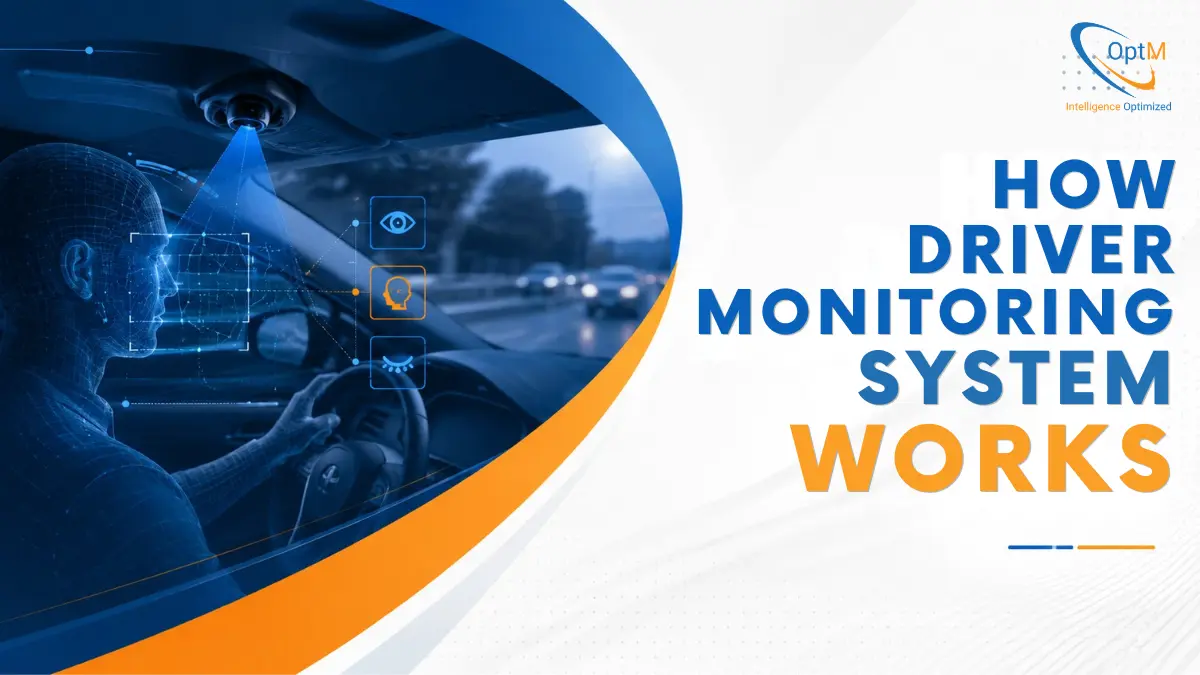
The actual operational loop of a driver monitoring system happens within milliseconds, continuously moving from raw optical capture to real-world safety logic. Understanding the complete Driver Monitoring System Architecture is critical to avoiding latency bottlenecks and ensuring deterministic processing.
The system executes a deep, mathematically rigorous four-stage engineering workflow:
[1. Optoelectronic Acquisition] → [2. Geometric Feature Extraction] → [3. Temporal State Classification] → [4. Protocol-Level HMI Triggering]
1. High-Frequency Optoelectronic Image Acquisition
The system begins at the hardware interface. The Near-Infrared (NIR) camera module captures a continuous stream of facial images, typically at 30 to 60 frames per second (fps).
To ensure consistent contrast under volatile lighting conditions—such as entering a dark tunnel or driving under high-glare midday sun—the camera works in tandem with pulsed NIR LEDs.
These LEDs flash in exact synchronization with the camera's global shutter sensor. This localized exposure allows the image sensor to filter out ambient visual noise and isolate the driver's face, projecting uniform illumination that effortlessly penetrates polarized sunglasses.
2. 3D Geometric Facial Landmark Extraction & Computer Vision
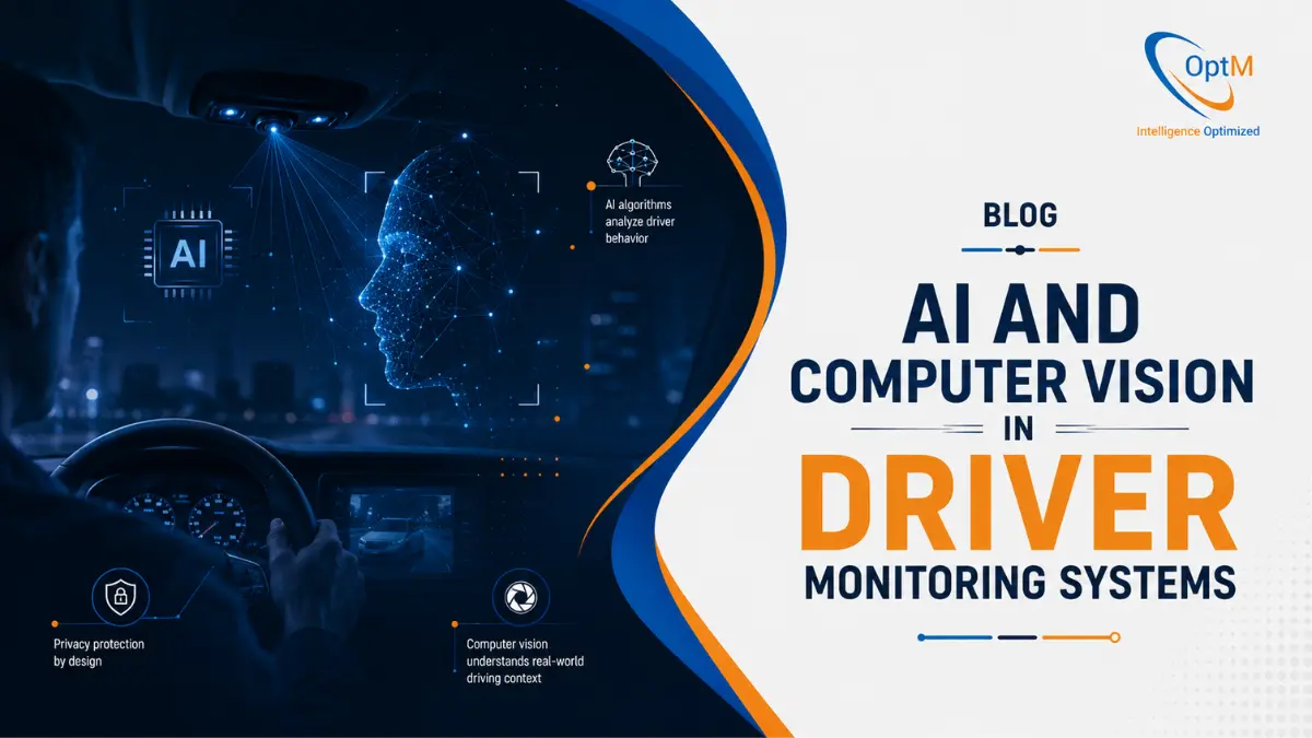
Once the raw pixel matrices enter the vision processing engine, advanced AI and Computer Vision in Driver Monitoring Systems extract structural information. The edge-based convolutional neural networks (CNNs) do not process the face as a static, flat image. Instead, they project a dynamic 3D geometric facial mesh.
- Landmark Initialization: The algorithms immediately track dozens of specific facial coordinate points, focusing on the jawline, nose bridge, eyebrows, eyelid margins, and corners of the eyes.
- Spatial Calibration: Because drivers vary in height and seat positioning, the system uses these tracking points to establish a three-dimensional geometric baseline. By constantly solving the perspective-n-point (PnP) problem, the software determines the precise spatial orientation of the driver's head relative to the camera sensor.
3. Temporal State Classification and Behavioral Analytics
With the 3D landmark mesh dynamically updating at 60Hz, the system routes the localized telemetry data through machine learning classifiers. This is where raw spatial points are converted into actionable safety metrics:
- Mathematical Fatigue Tracking (PERCLOS): Rather than triggering an alert for a single long blink, the algorithm calculates PERCLOS (Percentage of Eye Closure). It tracks the proportion of time that the driver's eyelids cover at least 80% of the pupil diameter over a moving temporal window (typically 30 to 60 seconds). If the cumulative PERCLOS score crosses a mathematically determined threshold, a fatigue event is generated.
- Gaze Vector & Coordinate Calculations: By calculating the exact geometric center of the pupil relative to the corneal reflection (the glint caused by the NIR LEDs), the software models a 3D gaze vector. This vector is mapped against a coordinate matrix representing the front windshield zone. If the gaze vector drifts away from this safe zone for more than 2.0 consecutive seconds, a distraction state is flagged.
- Head Pose Vector Metrics: Using spatial vectors for head rotation—measured across Pitch (nodding up/down), Yaw (turning left/right), and Roll (tilting side-to-side)—the system detects non-visual distraction. For instance, if a driver's head tilts down (negative Pitch) or turns toward the center console (positive or negative Yaw) while eyes are obscured from the camera's view, the system infers a micro-sleep or manual distraction event based on head posture alone.
4. Protocol-Level Communication and HMI Triggering
When an anomaly (fatigue or distraction) is confirmed by the temporal classifiers, the DMS ECU generates a safety command flag. This data is packaged into structured frames and transmitted instantly across the vehicle's high-speed internal bus networks, complying with CAN or J1939 communication protocols.
The destination for this network frame is the cockpit's human-machine interface (HMI). The signal instructs the system to execute a progressive safety workflow:
- Tier 1 Warning: Displays a subtle visual notification on a Qt-based Digital Instrument Cluster alongside a gentle audio chime.
- Tier 2 Escalation: If the driver's gaze vector does not return to the road within milliseconds, the system visual alerts escalate automatically to high-frequency haptic seat vibrations and louder alerts.
- Telematics Uplink: Simultaneously, the event is logged by the onboard Telematics Control Unit (TCU) and transmitted over high-speed LTE networks to provide automated, real-time risk reporting to fleet management dashboards on the cloud.
Detecting the Invisible: How DMS Identifies Drowsiness and Distraction
A common question engineers and safety managers face is: How exactly does a driver monitoring system detect subtle drowsiness before an accident happens?
The answer lies in how modern software models distinguish between normal, conscious driving behaviors and involuntary, fatigue-driven micro-sleeps.
| Behavioral Metric | Attentive Driving Baseline | Fatigue / Distraction Trigger |
|---|---|---|
| Average Blink Duration | 100 to 400 milliseconds | Exceeds 500 milliseconds (Micro-sleep) |
| Continuous Gaze Deviation | under 1.5 seconds off-road | > 2.0 seconds away from road path |
| Head Rotation (Pitch/Yaw) | Centered, slight micro-adjustments | Slumped downward or sustained side turn |
| Saccadic Eye Movements | Rapid, crisp focal shifts | Slow, sluggish eye movement transitions |
When an operator begins to tire, their saccadic eye movements (the quick, simultaneous movements of both eyes) slow down significantly. The system tracks these micro-behaviors alongside macro-movements like repetitive yawning or unnatural head-slumping. For a deeper breakdown of the mechanical and biological algorithms, read our comprehensive guide on How Driver Monitoring Systems Detect Drowsiness and Distraction.
The Network Ecosystem: How DMS Communicates with ADAS and Telematics
In modern automotive engineering, a DMS is not a standalone island; it functions as an essential context layer for the broader vehicle intelligence suite.
Bridging DMS and ADAS
Advanced Driver Assistance Systems (ADAS)—like lane-keeping assist (LKA) or automatic emergency braking (AEB)—monitor the environment outside the vehicle. The DMS monitors the environment inside the vehicle.
When these two architectures talk to one another, vehicle safety scales up dramatically. For instance, if an exterior radar senses a vehicle slowing down ahead, and the interior DMS reports that the driver's gaze vector has been directed downward at a phone for the last two seconds, the ADAS can choose to engage automatic emergency braking much earlier than it normally would. For a safety architecture to be truly predictive, engineering teams must master the precise sensor fusion and data handover of DMS vs ADAS during critical road events.
Moving Data to the Cloud
Beyond active localized braking or warnings, the DMS interfaces directly with telematics ecosystems. During a high-risk event, the DMS compresses the context data and routes it through a Telematics Control Unit (TCU) using high-speed LTE or 5G connectivity. This allows fleet managers to receive real-time driver risk scoring, deploy targeted safety coaching, and retain accurate liability records on a secure enterprise cloud backend.
Engineering Challenges and System Validation
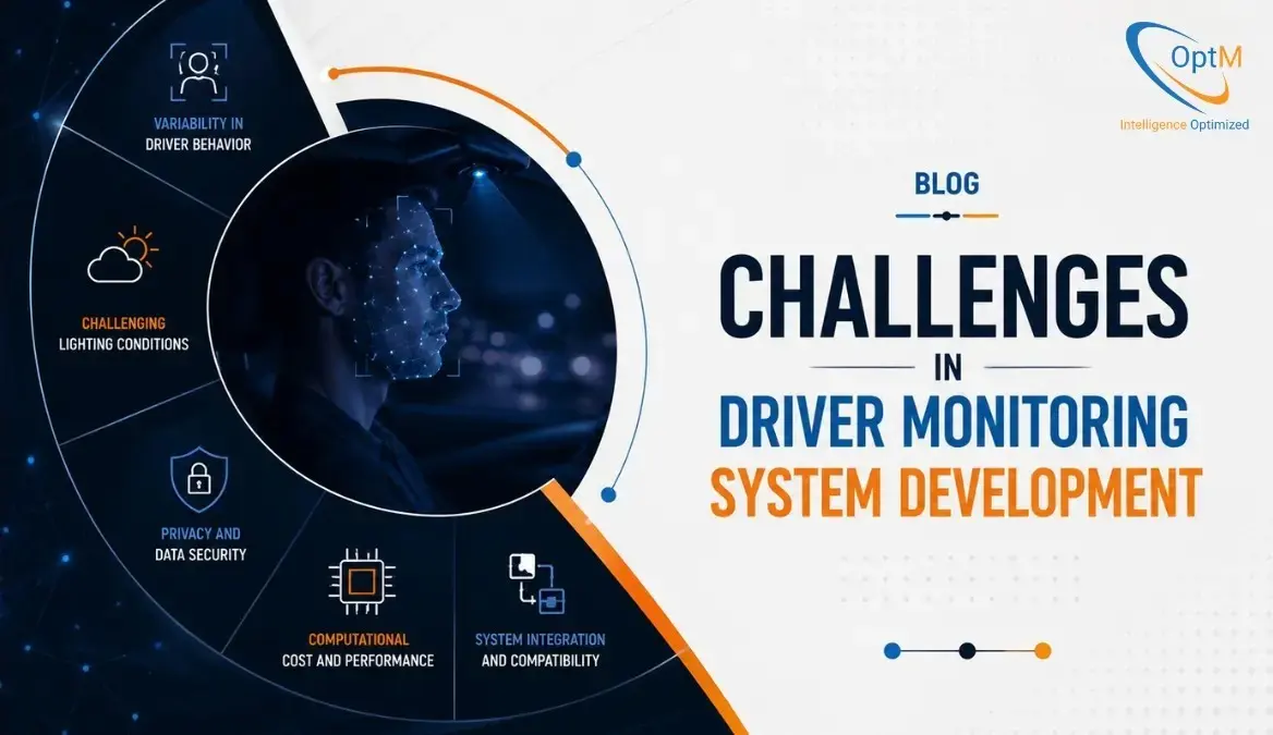
Building a system that works flawlessly inside a climate-controlled laboratory is one thing; ensuring it functions across millions of miles on the road is another. Engineering teams consistently run into severe real-world constraints when developing these systems.
Real-World Obstacles
- Thermal and Computational Budgets: Running continuous high-frame-rate computer vision models can cause small embedded ECUs to overheat quickly. Algorithms must be heavily optimized to execute on low-power hardware baselines without causing frame drops.
- Extreme Edge Cases: The software must maintain high accuracy regardless of whether the driver has facial hair, is wearing heavy winter gear, or is operating under rapidly changing shadows (such as driving through a forest or an urban high-rise environment).
To address these hurdles, development cycles must implement intense validation frameworks that test system latencies, graphical frame rates, and algorithm robustness across thousands of diverse driving profiles. Read more about these deployment workflows in Challenges in Driver Monitoring System Development and our deep dive into Driver Monitoring System Testing and Validation.
The Business Impact: Benefits for OEMs and Commercial Fleets
Investing in robust driver monitoring technologies yields distinct strategic advantages across the B2B automotive space:
- For Automotive OEMs: Integrating production-ready, low-latency DMS into your cabin architecture ensures immediate compliance with strict global safety mandates, helping your vehicle lines secure coveted 5-star safety ratings and protecting your brand's market share.
- For Commercial Fleet Operators: Actively mitigating driver fatigue directly reduces collision-related expenses, lowers asset downtime, and helps negotiate lower commercial insurance premiums by providing clear, data-backed proof of a proactive safety posture.
Beyond meeting regulatory mandates, calculating the long-term Benefits of Driver Monitoring System reveals a massive reduction in collision-related expenses and a measurable increase in commercial fleet uptime.
Frequently Asked Questions
Does a driver monitoring system record and store video footage?
In production-grade automotive applications, most advanced driver monitoring systems operate entirely on edge-processing architectures. This means the video frames captured by the camera are processed instantly in the volatile memory of the local ECU and immediately discarded. The system tracks numerical coordinates and behavioral states, rather than recording or streaming continuous raw video files, protecting driver privacy.
Can a DMS accurately track a driver who is wearing sunglasses?
Yes. Because modern systems rely on Near-Infrared (NIR) illumination and sensor arrays rather than visible light, the camera can easily penetrate the vast majority of polarized or tinted sunglass lenses to track pupil position, blink frequencies, and gaze deviation accurately in dark or changing environments.
Accelerating Your Automotive Safety Roadmap
Developing and integrating an automotive-grade Driver Monitoring System requires a deep, multidisciplinary approach—combining low-latency computer vision, power-optimized embedded firmware, and seamless integration with complex vehicle networks like CAN and J1939.
At OptM, our engineering teams focus on building and optimizing production-ready embedded software architectures, digital instrument clusters, and connected telematics environments tailored for global OEMs and commercial mobility platforms. We help you navigate the nuances of edge-AI processing and hardware abstraction so your safety systems deploy smoothly, run efficiently, and meet regulatory demands without exhausting your computational budgets.
Explore how our comprehensive engineering and product development teams can streamline your next vehicle platform. Review the OptM Driver Monitoring System engineering capabilities here.