
Content Writer & SEO Specialist
Content Writer & SEO Specialist
Aditya Sharma is a content writer at OptM Solutions specializing in automotive electronics, embedded systems, telematics, electric vehicle technologies, connected mobility, and autonomous driving technologies.
LinkedIn ProfileFor the past decade, automotive safety engineering has been obsessed with the exterior environment. Advanced Driver Assistance Systems (ADAS) have mapped the world outside the vehicle using complex arrays of radars, cameras, and LiDAR.
However, external environmental mapping solves only half of the collision equation. If a vehicle perfectly tracks a slowing truck ahead, but fails to recognize that the human operator is asleep, the system is fundamentally incomplete. This gap has led to the rapid acceleration of the Driver Monitoring System (DMS).
As the industry pushes into SAE Level 2+ and Level 3 autonomy, ADAS and DMS can no longer operate as isolated electronic islands. They must communicate. Before analyzing this integration, ensure you have a firm grasp of the foundational optical mechanics by reviewing exactly What is Driver Monitoring System technology at its baseline level.
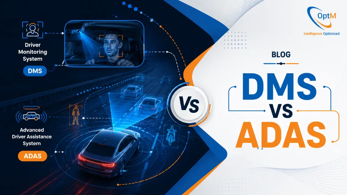
For embedded systems architects, Tier 1 suppliers, and validation engineers, understanding the precise differences, hardware requirements, and network integration strategies between DMS vs ADAS is the blueprint for next-generation vehicle platforms. Here is the definitive engineering breakdown of how these two safety networks operate, collide, and ultimately fuse.
1. The Core Paradigm: Outward Mapping vs. Inward Analytics
To understand how these systems fuse, you must define their isolated computational objectives. They share similar underlying computer vision mechanics, but their mathematical targets are entirely opposite.
Advanced Driver Assistance Systems (ADAS)
- The Objective: Environmental localization, object detection, and path planning.
- The Focus: The ADAS network maps a dynamic, unpredictable world. It must identify lane markings covered in snow, calculate the velocity of merging vehicles, classify pedestrians, and predict the trajectory of moving obstacles.
- The Output: Longitudinal control (accelerating/braking) and lateral control (steering actuation).
Driver Monitoring Systems (DMS)
- The Objective: Human physiological state classification and cognitive tracking.
- The Focus: The DMS network maps a highly constrained, relatively static environment (the vehicle cabin) to track a highly volatile subject (the human). It tracks microscopic biological markers—such as pupil dilation, micro-saccades, and spatial head pose.
- The Output: Deterministic risk metrics (fatigue levels, distraction states) and Human-Machine Interface (HMI) warning escalation.
2. The Hardware Divide: Optoelectronics and Sensing Modalities
Because ADAS and DMS are tracking entirely different environments, their physical sensor architectures are completely distinct.
ADAS Hardware Architecture
ADAS relies on a multi-modal sensor array. Because weather and lighting impact visibility, ADAS cannot rely on a single sensor type.
- RGB Vision Cameras: High-resolution sensors (often 8MP+) operating in the visible light spectrum to read speed limit signs, traffic lights, and lane geometries.
- Millimeter-Wave Radar (77 GHz): Projects radio waves to calculate the exact distance and relative velocity of metallic objects (like other cars), functioning perfectly in dense fog or heavy rain where cameras fail.
- LiDAR (Light Detection and Range): Fires millions of laser pulses per second to build a high-fidelity, 3D point-cloud map of the vehicle's surroundings, providing absolute depth perception.
DMS Hardware Architecture
The interior of a vehicle presents a unique optical challenge: blinding sunlight through the windshield, pitch-black darkness at night, and drivers wearing polarized sunglasses.
- Active Near-Infrared (NIR) Emitters: Unlike ADAS cameras that rely on ambient light, DMS generates its own invisible illumination. High-efficiency 940nm LEDs flood the cabin, penetrating tinted glasses and ensuring consistent facial contrast regardless of the time of day.
- Global Shutter Sensors: ADAS cameras tracking distant objects can sometimes use rolling shutters. DMS requires global shutter sensors that expose every pixel simultaneously. This freezes the driver's face at 60 frames per second, eliminating the motion blur caused by rapid head turns or sudden braking.
Selecting the proper global shutters and specific NIR wavelengths is a critical design phase when engineering a scalable Driver Monitoring System Architecture.
3. Algorithmic Processing: Path Planning vs. Cognitive Tracking
The edge AI running on the respective Electronic Control Units (ECUs) executes fundamentally different mathematical pipelines.
The ADAS Algorithm: Time-To-Collision (TTC)
ADAS algorithms are obsessed with spatial geometry and physics. The core metric is the Time-To-Collision (TTC).
By fusing radar velocity data with camera bounding boxes, the ADAS ECU continuously calculates:
Time-To-Collision (TTC) = Distance to Target / Relative Velocity
If the TTC drops below a pre-calibrated safety margin (e.g., 2.5 seconds), the ADAS triggers the Automatic Emergency Braking (AEB) actuator.
The DMS Algorithm: PERCLOS and Gaze Vectoring
The DMS algorithm is obsessed with biomechanics. It does not care how fast the car is moving; it cares about the operator's central nervous system.
- PERCLOS (Percentage of Eye Closure): The algorithm calculates the exact pixel distance between the upper and lower eyelids. It measures the percentage of time the eyes are more than 80% closed over a rolling 60-second temporal window to classify severe fatigue.
- 3D Gaze Vectoring: The system solves the Perspective-n-Point (PnP) problem, building a dynamic 3D facial mesh. By tracking the exact X, Y, and Z coordinates of the pupil against the stationary infrared glint on the cornea, it calculates exactly where the driver is looking.
For a deeper dive into the specific math and part-based tracking models running on the NPU, explore our comprehensive breakdown of AI and Computer Vision in Driver Monitoring Systems.
4. The "Automation Complacency" Problem
Why is the automotive industry suddenly forcing these two systems together? The answer lies in human psychology and the danger of Level 2+ autonomy.
When ADAS is highly capable (e.g., adaptive cruise control combined with auto-steer on a highway), human drivers experience Automation Complacency. Because the car is doing 95% of the work, the driver's brain naturally disengages. They check their phones, turn around to look at passengers, or fall asleep.
However, in Level 2 systems, the human is still legally required to monitor the environment. If the ADAS camera is blinded by the sun, the system will disengage and hand control back to the driver. If the driver is looking at their phone, the vehicle will crash.
This is why ADAS cannot survive without DMS. The DMS acts as the psychological anchor, forcing the human operator to remain engaged in the driving task, even when the ADAS is handling the physical actuation. Tracking these subtle physiological shifts is complex, which is why understanding How Driver Monitoring Systems Detect Drowsiness and Distraction is critical for preventing Level 2 system abuse.
5. Sensor Fusion: The Handoff Matrix
The holy grail of modern vehicle architecture is Sensor Fusion—when the ADAS ECU and the DMS ECU stop acting as isolated nodes and begin sharing data across the vehicle's network bus.
When these systems fuse, the vehicle achieves true situational awareness.
Engineering the Dynamic AEB Threshold
In a legacy, un-fused vehicle, the Autonomous Emergency Braking (AEB) module acts blindly. It assumes the driver is paying attention. It waits until the absolute last millisecond to slam on the brakes, hoping the human will intervene first.
In a fused architecture, the ADAS module dynamically alters its physics equations based on the driver's cognitive state.
- Scenario A (Attentive Driver): The ADAS radar detects a stopped car ahead. It checks the internal CAN-FD network. The DMS broadcasts that the driver's 3D gaze vector is locked onto the windshield. The ADAS delays braking, allowing the driver to smoothly apply the brakes themselves.
- Scenario B (Distracted Driver): The ADAS radar detects the same stopped car. It checks the CAN bus. The DMS broadcasts that the driver's gaze vector has been pointed at their lap for 2.2 seconds. The ADAS module knows the human is compromised. It instantly drops its Time-To-Collision (TTC) threshold, violently engaging the AEB module a full second earlier to prevent a fatal impact.
The Mathematics of Fused Intervention
The integrated safety loop can be represented by adjusting the required deceleration a_req based on the cognitive attention score C_att:
Deceleration (a_req) = f( v_rel^2 / (2 * (d - d_safe)), C_att )
Where a low C_att (distracted driver) geometrically increases the required early deceleration triggered by the ADAS controller.
Integrating these dynamic braking thresholds introduces massive validation hurdles, compounding the existing Challenges in Driver Monitoring System Development for Tier 1 suppliers.
6. Network Topology and Timestamp Synchronization
Achieving this flawless sensor fusion requires overcoming massive embedded networking bottlenecks. You cannot simply plug both ECUs into the dashboard and hope they synchronize.
The Synchronization Challenge
If the ADAS radar detects a hazard at exactly 12:00:00.050, it needs to know what the driver was doing at that exact millisecond. If the DMS camera feed is lagging by 100 milliseconds due to a slow processor, the ADAS might receive outdated telemetry, assuming the driver is attentive when they have actually just closed their eyes.
The Engineering Solution: Precision Time Protocol (PTP)
To solve this, advanced Cockpit Domain Controllers utilize the IEEE 802.1AS Precision Time Protocol (PTP) routed over Automotive Ethernet.
Unlike legacy CAN buses, Automotive Ethernet provides multi-gigabit bandwidth. PTP acts as a master-slave clock synchronization mechanism. It ensures that every single frame captured by the exterior ADAS cameras and the interior DMS NIR sensor receives an identical, microsecond-accurate global hardware timestamp.
When the Sensor Fusion Core processes the data, it perfectly aligns the external threat vector with the internal physiological state, executing a flawless, deterministic safety intervention.
7. The Take-Over Request (TOR) in Level 3 Autonomy
As vehicles transition to SAE Level 3 autonomy, the legal liability shifts. In Level 3, the car is officially "driving" itself under specific conditions (like a traffic jam). The driver is legally permitted to take their hands off the wheel and watch a movie.
However, when the traffic jam ends, the ADAS must hand control back to the human. This is known as the Take-Over Request (TOR).
In Level 3, DMS is the legal bridge. The ADAS cannot simply turn off. It must query the DMS: "Is the driver awake? Are their hands back on the wheel? Are their eyes looking forward?"
Only when the DMS confirms the human has regained full cognitive and physical situational awareness will the ADAS execute a safe relinquishment of vehicle control.
Frequently Asked Questions
Can a single centralized SoC run both ADAS and DMS?
Yes. Modern architectures are moving away from distributed ECUs toward centralized Domain Controllers. High-performance SoCs handle exterior path planning and interior vision tracking simultaneously. Engineers use strict hardware hypervisors to partition the silicon, ensuring the heavy neural networks of the ADAS do not throttle or crash the critical safety loops of the DMS.
Which system takes priority if they conflict?
In safety-critical architectures, active collision avoidance (ADAS) always takes ultimate actuation priority. If the DMS detects the driver is perfectly attentive, but the ADAS radar detects a child running into the street, the AEB will override the human and brake the vehicle.
Why does DMS use CAN-FD while ADAS often requires Automotive Ethernet?
ADAS sensors (like 8MP cameras and high-density LiDAR) generate massive payloads of raw environmental data, requiring the gigabit speeds of Automotive Ethernet. A standalone DMS processes the heavy video data locally at the edge. The resulting output is merely a few bytes of mathematical coordinates and risk flags (e.g., "Fatigue = High"). This highly compressed data easily travels over the lightweight, deterministic CAN-FD bus.
Will Occupant Monitoring Systems (OMS) replace DMS?
No, OMS is an expansion, not a replacement. While DMS focuses entirely on the driver using a narrow-field-of-view camera on the steering column, OMS uses wide-angle cabin cameras to track passenger seating positions, child seats, and seatbelt usage. Future architectures will fuse both into a single Cabin Monitoring System (CMS) ECU.
Engineer Your Next-Generation Sensor Fusion Architecture
The wall between internal cabin safety and external environmental mapping has fallen. For an autonomous vehicle to achieve flawless situational awareness, its ADAS and DMS must execute a perfect, microsecond-accurate data handshake. Architecting this fusion requires profound expertise in RTOS optimization, embedded computer vision, and deterministic network routing.
Explore how our embedded engineering teams can streamline your hardware integration, optimize your NPU workloads, and accelerate your functional safety compliance. Review our production-ready Driver Monitoring System solutions today to elevate your intelligent cabin architecture.