
Content Writer & SEO Specialist
Content Writer & SEO Specialist
Aditya Sharma is a content writer at OptM Solutions specializing in automotive electronics, embedded systems, telematics, electric vehicle technologies, connected mobility, and autonomous driving technologies.
LinkedIn ProfileBuilding a safety-critical internal vision network is not an exercise in off-the-shelf part assembly. For an OEM or Tier 1 supplier, selecting the right physical hardware dictates the absolute thermal, latency, and reliability ceilings of the entire vehicle platform.
When evaluating What is Driver Monitoring System technology at the bare-metal level, you are looking at a highly synchronized orchestration of optoelectronics, high-speed data interconnects, localized neural processing silicon, and deterministic networking gateways. A single bottleneck—such as choosing a rolling shutter over a global shutter, or miscalculating the thermal dissipation of a Neural Processing Unit—will cause a catastrophic failure in the system's safety loop.
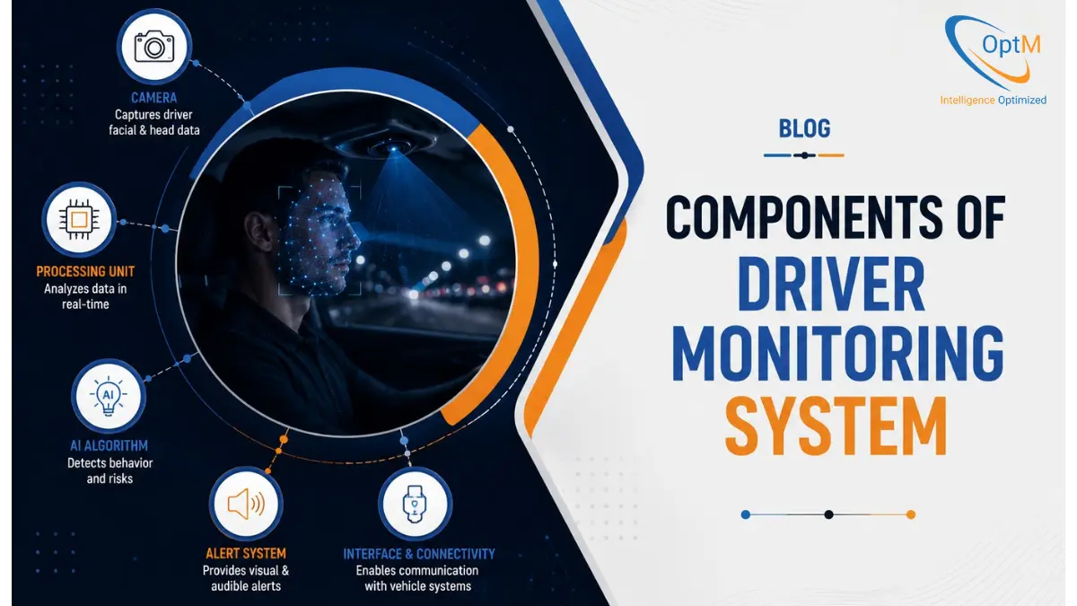
This technical manual deconstructs the exact physical and logical components of Driver Monitoring System hardware. From the photon capture at the lens to the CAN-FD frame broadcast on the vehicle bus, here is the complete engineering blueprint.
1. The Optoelectronic Acquisition Module (The Eye)
Before any software can run, the system must acquire high-fidelity, illumination-invariant data from a highly volatile physical environment. The camera module is a complex sub-assembly containing specific optoelectronic hardware designed entirely around the Near-Infrared (NIR) spectrum.
Active Near-Infrared (NIR) Emitters
A vehicle cabin can pitch from absolute darkness to blinding direct sunlight in seconds. To maintain a constant visual baseline, the system projects its own light using Vertical-Cavity Surface-Emitting Lasers (VCSELs) or specialized NIR Light Emitting Diodes (LEDs).
- Wavelength Selection (850nm vs. 940nm): While 850nm LEDs offer higher camera sensitivity, they produce a faint, dull red glow visible to the human eye, which distracts drivers in dark cabins. Production-grade systems predominantly use 940nm VCSELs. This wavelength is completely invisible to human vision, penetrates polarized sunglasses flawlessly, and creates a high-contrast corneal glint required for gaze tracking.
- Pulse Synchronization: These emitters do not stay on continuously (which would melt the plastic housing). They are strobed in exact microsecond synchronization with the camera sensor's exposure window, maximizing optical power while minimizing thermal output.
Optical Lenses and Bandpass Filters
The lens assembly (typically a multi-element glass or high-grade polycarbonate stack) focuses the returning NIR photons onto the image sensor.
- Narrowband IR Filters: To prevent the sensor from being blinded by visible sunlight, the lens is coated with a strict dielectric bandpass filter. This filter aggressively rejects all visible light (400nm–700nm) and only allows photons at exactly the 940nm (+/- 10nm) wavelength to pass through.
- Field of View (FOV): The lens is engineered with a specific FOV—typically between 60° and 120° diagonally—depending on whether the camera is mounted on the steering column (narrow FOV) or the central infotainment cluster (wide FOV).
The CMOS Image Sensor: Global Shutter
This is the most critical hardware choice in the acquisition layer. Utilizing a standard Rolling Shutter sensor (used in smartphones) is a fatal engineering error. Rolling shutters expose the pixel matrix row-by-row. If the vehicle hits a pothole or the driver snaps their head, the resulting image is geometrically skewed (the "Jello Effect"), which instantly breaks the 3D facial mesh algorithms.
- Global Shutter Architecture: DMS modules utilize automotive-grade CMOS Global Shutter sensors. Every single pixel in the matrix is exposed to light and read simultaneously. This physically freezes rapid micro-movements at 60 frames per second (fps).
- Quantum Efficiency (QE): The sensor must have a high QE at the 940nm wavelength—meaning it efficiently converts invisible NIR photons into electrical electrons—minimizing electronic noise in pitch-black conditions.
2. High-Speed Serial Interconnects (The Optic Nerve)
Once the CMOS sensor converts photons into a digital pixel matrix, that massive payload of uncompressed data must travel from the camera module (e.g., on the steering column) to the processing unit (ECU).
To calculate the required bandwidth, engineers use the uncompressed data rate formula:
Bandwidth = Resolution_width * Resolution_height * Bit Depth * Frame Rate
A 2-Megapixel sensor running at 60fps with a 12-bit depth generates over 1.4 Gigabits of raw data per second. Standard wiring harnesses cannot handle this.
SerDes (Serializer/Deserializer) Chips
The data is fed into a Serializer IC located inside the camera housing. Protocols like GMSL2/3 (Gigabit Multimedia Serial Link) or FPD-Link III/IV (Flat Panel Display Link) compress this massive parallel data stream into a single high-speed serial bitstream.
- Coaxial Transmission: The serialized data travels over a single lightweight coaxial cable to the main processing board. This single cable also provides Power-over-Coax (PoC), supplying voltage to the camera and LEDs without requiring a separate, heavy power harness.
- Deserialization: Upon reaching the edge compute node, a Deserializer IC unpacks the stream back into a parallel format, feeding it directly into the processor via the MIPI CSI-2 (Camera Serial Interface) port.
Understanding the routing and limitations of these high-speed links is a fundamental part of designing a stable Driver Monitoring System Architecture, ensuring data integrity across long vehicle chassis lengths.
3. The Edge Compute Node and Silicon (The Brain)
This is the physical computing hardware—the System-on-Chip (SoC) or standalone Electronic Control Unit (ECU)—where the mathematical intelligence lives. Because routing uncompressed video to the cloud is impossible due to network latency and data privacy laws, 100% of the computation must happen at the "edge" on local silicon.
The Hardware Image Signal Processor (ISP)
Before the AI can read the image, the raw Bayer or monochrome data from the sensor must be digitally developed. The hardware ISP is a dedicated silicon block on the SoC responsible for cleaning the image.
- Auto-Exposure and Gain Control: If the vehicle exits a dark tunnel into blinding snow, the ISP executes microsecond exposure adjustments to prevent the image from washing out.
- Tone Mapping and Defect Pixel Correction: It mathematically removes thermal noise and corrects dead pixels, delivering a mathematically perfect, high-contrast grayscale frame to the neural network.
The Neural Processing Unit (NPU / Deep Learning Accelerator)
Standard CPUs are highly inefficient at running computer vision algorithms. They consume too much power and generate too much heat.
- Matrix Multiplication: The SoC features a dedicated hardware NPU explicitly designed to execute the millions of multiply-accumulate (MAC) operations required by Convolutional Neural Networks (CNNs).
- INT8 Quantization: To survive the strict thermal limits of an enclosed dashboard, engineers quantize the heavy 32-bit floating-point models down to 8-bit integers (INT8). The NPU processes these lightweight INT8 models at 60fps while drawing minimal wattage.
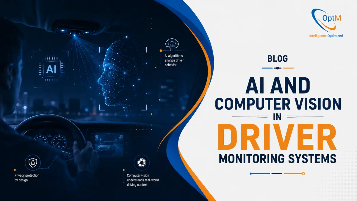
This specialized silicon is what makes the execution of deep AI and Computer Vision in Driver Monitoring Systems possible within a vehicle's thermal constraints.
The Safety Microcontroller Unit (MCU)
While the NPU handles the heavy AI math, a dedicated, highly reliable MCU core (typically an ARM Cortex-R series) oversees the functional safety of the system.
- ASIL Compliance: The MCU operates as the watchdog. It continuously runs Built-In Self-Tests (BIST). If the NPU crashes, or if the camera lens is blocked, the MCU catches the fault and triggers an ASIL-compliant diagnostic failure protocol.
4. The Core Software and Memory Stack
Hardware is useless without the low-level firmware and high-level behavioral algorithms directing the logic.
Volatile Memory (LPDDR4 / LPDDR5)
Running heavy computer vision models requires massive memory bandwidth. The SoC is paired with automotive-grade Low-Power Double Data Rate (LPDDR) RAM. This memory must endure the extreme vibrations and temperature swings of the vehicle cabin without dropping data bits.
The Real-Time Operating System (RTOS)
General-purpose operating systems (like standard Linux or Android) are not allowed in safety-critical loops due to unpredictable task scheduling. The hardware runs on a deterministic RTOS (like QNX or specific AUTOSAR Classic profiles). This guarantees that the eye-tracking loop executes every 16.6 milliseconds, regardless of what else the processor is doing.
The Application Layer (Vision Algorithms)
This is where the mathematical classification happens. The software maps the 3D facial geometry, tracks pupil vectors, and calculates temporal closure rates. This specific software component defines exactly How Driver Monitoring Systems Detect Drowsiness and Distraction, translating physical pixels into actionable human behavioral metrics like PERCLOS.
5. Vehicle Network Gateways (The Spine)
Once the localized SoC decides that the driver is asleep or dangerously distracted, that data must leave the isolated component and interface with the vehicle's broader nervous system.
CAN-FD and Automotive Ethernet Controllers
The SoC integrates specific hardware transceivers to broadcast data over the vehicle bus.
- The Output Frame: The DMS does not send video over the network. It packages the finding into a deterministic binary flag (e.g.,
Risk_Level = High; Gaze_Zone = Lap). - Routing the Payload: This payload is pushed through a CAN-FD (Controller Area Network Flexible Data-Rate) transceiver. Because this is a high-priority safety flag, the CAN controller assigns it network dominance, forcing lower-priority data (like AC temperature updates) to wait.
For advanced vehicles integrating multiple exterior radars, this gateway is where the internal data collides with the external environment, forming the hardware basis for understanding the integration of DMS vs ADAS and enabling unified autonomous braking decisions.
6. Human-Machine Interface (HMI) Actuators (The Reflexes)
The final component of the system is the actuation hardware—the physical mechanisms used to rip the driver's attention back to the road. This requires a tiered hardware escalation strategy.
The Digital Instrument Cluster
The CAN-FD alert frame is intercepted by the vehicle's Cockpit Domain Controller, which commands the dashboard display. Using embedded UI frameworks (like Qt), the dashboard hardware instantly renders high-contrast visual warnings, flashing specific graphical icons directly in the driver's line of sight.
Audio DSPs and Spatial Chimes
Simultaneously, the alert routes through the vehicle's Audio Digital Signal Processor (DSP). Instead of a generic beep, modern systems execute spatial audio routing—pushing a high-frequency, jarring chime specifically through the driver-side headrest speakers to ensure immediate cognitive recognition.
Haptic Feedback Motors
If visual and auditory warnings fail to break a micro-sleep, the system engages physical hardware. Haptic actuators embedded within the steering wheel column or the seat track engage, delivering aggressive, physical vibrations designed to instantly spike the driver's adrenaline and restore physical control of the vehicle.
Integrating and Validating the Hardware Ecosystem
Sourcing these individual components—from the 940nm VCSELs to the LPDDR5 memory modules—is a complex supply chain challenge. However, the true engineering bottleneck is proving that this bespoke hardware combination will not fail or overheat during real-world execution.
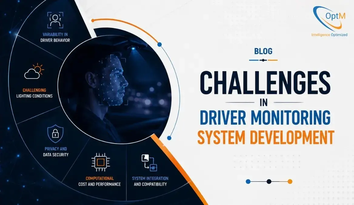
When an OEM attempts to fuse these physical layers, they inevitably crash into strict thermal limits, lens occlusion anomalies, and functional safety constraints. Overcoming these specific Challenges in Driver Monitoring System Development requires optimizing the low-level firmware at the assembly level to ensure the silicon does not bottleneck the optical feed.
Furthermore, before a single vehicle can be sold to a consumer, every component in this hardware chain must survive thousands of hours of rigorous stress. Passing strict Euro NCAP and GSR regulations requires a massive investment in Driver Monitoring System Testing and Validation, utilizing specialized HIL (Hardware-in-the-Loop) rigs to prove the optical sensors and NPUs maintain their deterministic timing under extreme thermal loads.
Explore how our embedded software architects can optimize your hardware topology, streamline your NPU execution, and eliminate integration bottlenecks. Review our production-ready Driver Monitoring System solutions today to elevate your intelligent cabin architecture.
Frequently Asked Questions
Why can't standard RGB dashboard cameras be repurposed for Driver Monitoring Systems?
Standard RGB cameras rely on visible light. They are virtually blind in pitch-black vehicle cabins at night and are easily blinded by sudden glare (like exiting a tunnel). Furthermore, RGB sensors typically use rolling shutters, which create severe motion blur when the vehicle vibrates or the driver turns their head. DMS requires Near-Infrared (NIR) sensors with global shutters to capture high-contrast, motion-free facial geometry regardless of ambient lighting.
Why is AEC-Q100 certification mandatory for DMS silicon components?
Consumer-grade silicon (like the chips in a smartphone) is designed to operate between 0°C and 35°C. The interior of a car parked in the desert can reach 85°C (185°F), and drop to -40°C in winter. AEC-Q100 is a failure-mechanism-based stress test qualification for packaged integrated circuits. Components in a DMS—from the image sensor to the NPU—must be AEC-Q100 Grade 2 or Grade 1 certified to guarantee they will not physically degrade, warp, or thermal-throttle during extreme environmental exposure.
How do engineers protect the high-speed camera data from Electromagnetic Interference (EMI) within the vehicle?
A vehicle chassis is an electromagnetically noisy environment, filled with high-voltage battery cables, Wi-Fi antennas, and Bluetooth transceivers. To prevent this noise from corrupting the uncompressed video stream, the SerDes interconnects utilize heavily shielded coaxial cables. Furthermore, the Serializer/Deserializer chips are designed to pass strict CISPR 25 EMI/EMC standards, ensuring the camera data reaches the SoC without dropped packets or bit-flips.
Why use a dedicated Neural Processing Unit (NPU) instead of just running the AI on a powerful CPU?
Running convolutional neural networks (CNNs) requires millions of Multiply-Accumulate (MAC) operations per frame. A standard CPU processes these operations sequentially, drawing massive amounts of power and generating fatal levels of heat. An NPU is a specialized hardware accelerator built specifically for parallel matrix multiplication. By using an NPU, the SoC can execute the heavy computer vision workloads at 60fps while drawing a fraction of the wattage, keeping the enclosed hardware within its strict thermal budget.