
Content Writer & SEO Specialist
Content Writer & SEO Specialist
Aditya Sharma is a content writer at OptM Solutions specializing in automotive electronics, embedded systems, telematics, electric vehicle technologies, connected mobility, and autonomous driving technologies.
LinkedIn ProfileThe software-defined vehicle requires an internal nervous system just as sophisticated as its external sensing arrays. While radars and LiDAR track the road, the internal cabin environment presents a highly volatile, unstructured data set: human physiology.
For original equipment manufacturers (OEMs) and Tier 1 suppliers, transitioning a driver monitoring algorithm from a laboratory environment into a mass-production vehicle is a monumental engineering challenge. A production-grade system is not merely an optical sensor wired to a display. It is a safety-critical embedded architecture that spans high-frequency optoelectronics, complex Image Signal Processors (ISPs), Neural Processing Units (NPUs), and deterministic vehicle network protocols.
Understanding the underlying structural topology of this technology is vital. It dictates how hardware and software must interface to ensure zero-latency safety interventions.
What is Driver Monitoring System Architecture?
Driver Monitoring System Architecture is the multi-layered hardware and software framework that governs in-cabin vision processing. It dictates how raw optical data is captured via near-infrared sensors, processed through localized edge-AI pipelines, and converted into deterministic vehicle control commands over automotive networks like CAN-FD or Automotive Ethernet to execute safety interventions.
Before mapping the specific network topologies and ASIL compliance requirements, engineering teams must establish a firm baseline of exactly What is Driver Monitoring System technology executing at the protocol level.
The 4-Stage Execution Pipeline: From Photons to Protocols
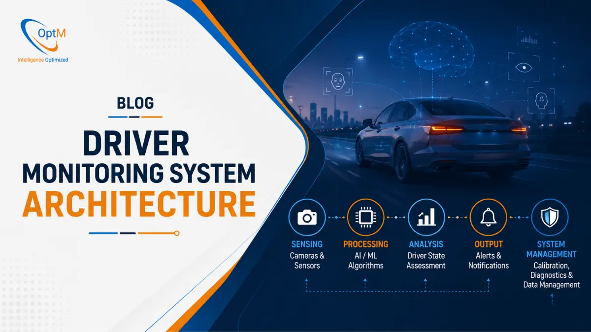
A production-ready architecture must operate deterministically within milliseconds. To achieve this, the system is organized into four distinct structural layers. Moving from the physical cabin environment to the vehicle's electronic control loop, each layer must execute its function flawlessly without bottlenecking the next.
Layer 1: Optoelectronic Data Acquisition
The architecture begins with the physical sensors responsible for gathering high-fidelity data. Standard RGB image sensors fail during nighttime operation or when a driver wears polarized sunglasses, requiring a specialized optoelectronic hardware approach to capture usable data.
- Active NIR Illumination & Global Shutters: The system utilizes pulsed Near-Infrared (NIR) emitters (850nm or 940nm) synchronized perfectly with global shutter image sensors. This prevents motion blur during rapid head turns and penetrates dark lenses without blinding the driver.
- MIPI CSI-2 Data Transmission: The raw pixel matrices are transmitted from the camera module to the host processor using the Mobile Industry Processor Interface (MIPI) Camera Serial Interface 2 (CSI-2), ensuring massive bandwidth and ultra-low latency data transfer. Integrating the correct Components of Driver Monitoring System hardware at this layer is what defines the system's baseline reliability.
Layer 2: Hardware Abstraction and OS Baseline
Once the raw pixel data hits the Electronic Control Unit (ECU) or domain controller, it enters the system software layer. Because driver monitoring is a safety-critical function, the architecture cannot rely on standard, general-purpose operating systems that suffer from unpredictable task scheduling.
- Real-Time Operating Systems (RTOS): The architecture utilizes a deterministic RTOS (like QNX or embedded Linux) to guarantee that critical vision-processing threads are executed with strict timing parameters, never delayed by lower-priority infotainment tasks.
- AUTOSAR Compliance: The software architecture is built on AUTOSAR (Automotive Open System Architecture) standards. This modular approach abstracts the hardware from the software, allowing Tier 1 suppliers to scale the monitoring application across different microcontrollers (MCUs) without rewriting the core logic.
Layer 3: Edge Computing and Neural Network Execution
This software layer functions as the analytical core of the system. Rather than sending video to the cloud—which introduces unacceptable network latency and fatal privacy vulnerabilities—the system processes the visual data locally, transforming raw pixels into structured mathematical telemetry.
- Image Signal Processing (ISP): The raw data is first processed by a dedicated hardware ISP, which handles auto-exposure, noise reduction, and high dynamic range (HDR) adjustments, ensuring the image is perfectly tuned for the neural network even when exiting a dark tunnel into direct sunlight.
- NPU Execution Pipeline: The tuned frames are fed into a Neural Processing Unit (NPU). Here, convolutional neural networks calculate spatial head pose (Pitch/Yaw/Roll) and extract precise eyelid margins. Mastering this edge-computing pipeline is critical for engineers studying How Driver Monitoring Systems Detect Drowsiness and Distraction in dynamic highway environments.
Layer 4: Network Broadcasting and HMI Rendering
Once the neural processing unit confirms a severe distraction or fatigue anomaly, the architecture must transition from analysis to action. The ECU packages the behavioral metrics into deterministic command frames and routes them out of the SoC to the vehicle's broader nervous system.
- Automotive Ethernet and CAN-FD Routing: The system transmits high-priority interrupt signals over CAN-FD or Automotive Ethernet. This ensures the safety flag reaches the braking and warning modules instantly without packet collision or network latency.
- Qt-Based Cockpit Execution: The command frame is intercepted by the digital instrument cluster. Using embedded graphical frameworks, the HMI renders immediate, high-framerate visual warnings and escalates to audio DSP chimes, ensuring the driver is alerted instantly.
Architectural Topologies: Standalone vs. Domain vs. Zonal
When an OEM designs a new vehicle platform, procurement and engineering teams face a critical structural decision regarding where the compute actually lives. The industry is currently transitioning through three distinct architectural phases.
1. Distributed / Standalone Architecture
In legacy and many current production vehicles, the architecture uses a standalone Electronic Control Unit. The camera module is hardwired directly to a dedicated ECU housed within the dashboard or rearview mirror.
- Advantages: This creates a perfectly isolated safety loop. It is highly secure, easier to certify for strict ASIL (Automotive Safety Integrity Level) compliance, and simplifies thermal management because the processor only handles one task.
- Disadvantages: It adds significant weight to the vehicle's wiring harness, increases the Bill of Materials (BOM) cost, and makes over-the-air (OTA) software updates cumbersome.
2. Cockpit Domain Controller Architecture
Modern software-defined vehicles are consolidating. Instead of a dedicated ECU, the camera feeds data directly into a centralized Cockpit Domain Controller—a massive SoC that runs the digital instrument cluster, the infotainment system, and the interior monitoring simultaneously.
- Advantages: Massive cost savings on physical hardware and wiring. It allows for deep, native integration, seamlessly bridging the safety system with the cabin's media and climate controls.
- Disadvantages: High software complexity. Because safety-critical monitoring is sharing silicon with non-safety features (like Android Automotive media players), engineers must utilize strict hardware hypervisors to partition the SoC. If the infotainment screen crashes, the hypervisor ensures the RTOS running the safety loop remains completely unaffected.
3. Zonal Architecture (The Future Standard)
Looking toward 2026 and beyond, OEMs are shifting to Zonal architectures. In this topology, the camera is treated purely as a "dumb" sensor. It plugs into a local, high-speed Zonal Gateway located near the windshield. The gateway passes the raw data over Automotive Ethernet to a central vehicle supercomputer where the AI processing occurs. This approach dramatically reduces wiring weight and centralizes all vehicle intelligence, but requires flawless, ultra-high-bandwidth internal networks.
System Integration: The Sensor Fusion Matrix
An optimized architecture ensures that cabin telemetry does not exist in an isolated vacuum. For a vehicle to achieve true situational awareness, the internal monitoring setup must achieve flawless sensor fusion with exterior ADAS modules.
When evaluating the data handshake of DMS vs ADAS, the value of a shared network architecture becomes clear. Exterior sensors only know what is happening on the road; they do not know if the driver is prepared to react.
If the forward-facing exterior radar detects a rapidly decelerating truck, the vehicle's domain controller instantly checks the internal network bus for driver attentiveness. If the architecture confirms the driver's 3D gaze vector is pointed down at a smartphone, the system alters its parameters. It instructs the Autonomous Emergency Braking (AEB) module to drop its intervention threshold and forcefully apply the brakes much earlier than it would for an attentive driver.
Overcoming Hardware Bottlenecks and Functional Safety
Transforming a theoretical architecture blueprint into a production-ready vehicle platform introduces significant structural hurdles. A primary obstacle is thermal throttling.
Running convolutional neural networks at 60 frames per second generates massive computational heat. If the SoC overheats, it drops frames, and the safety loop fails. Automotive teams must optimize the software at the assembly level, utilizing hardware accelerators to execute the math efficiently without exhausting the ECU's computing budget.
Furthermore, the entire architecture must comply with ISO 26262 functional safety standards. The system is typically required to meet ASIL B ratings, meaning the hardware and software must possess built-in redundancies. If the optical sensor is blocked by a hand, or if an LED emitter fails, the architecture must instantly execute a Built-In Self-Test (BIST), diagnose the failure, and flag an error on the CAN bus rather than simply shutting down silently.
Navigating these thermal limits and compliance standards is the core reality of overcoming Challenges in Driver Monitoring System Development for mass-market deployment. Engineers must execute thousands of hours of Driver Monitoring System Testing and Validation across extreme environmental conditions to guarantee the architecture holds up under stress.
Frequently Asked Questions
Does a Domain Controller architecture compromise ASIL safety ratings?
No, provided it utilizes strict hardware virtualization. By using a hypervisor, engineers partition the main SoC. The safety-critical pipeline runs securely on a dedicated RTOS core (achieving ASIL B or ASIL D compliance), completely isolated from the ASIL QM (Quality Management) infotainment OS.
Why is edge computing mandatory over cloud processing?
Processing vision data at the edge ensures sub-millisecond execution latencies, which are essential for triggering safety warnings during highway emergency scenarios. It also completely protects operator data privacy and guarantees system operation in remote geographical regions with zero cellular connectivity.
How does the system handle sudden ambient light changes?
The architecture relies heavily on the hardware Image Signal Processor (ISP). When a vehicle exits a pitch-black tunnel into direct midday sunlight, the ISP executes auto-exposure and high dynamic range (HDR) corrections in microseconds, ensuring the neural network receives a perfectly balanced frame without losing its tracking lock on the driver's face.
What is the role of Automotive Ethernet in modern architectures?
As camera resolutions scale to 2MP and 5MP to track subtler eye movements, legacy CAN networks lack the bandwidth to handle the data payloads. Automotive Ethernet provides multi-gigabit speeds, allowing uncompressed, high-fidelity sensor data to route from the camera module to the central compute nodes instantaneously.
Architect Your Next-Generation Cabin Infrastructure
Designing an autonomous-ready cabin demands profound expertise in low-level firmware engineering, high-frequency computer vision optimization, and rigorous hardware-software integration. Navigating the delicate balance between processing budgets, thermal boundaries, and ISO 26262 compliance is a monumental development hurdle.
At OptM, our embedded engineering teams bridge the gap between theoretical architecture and production-grade reality. We help global OEMs and Tier 1 suppliers build, validate, and deploy intelligent automotive software ecosystems that integrate flawlessly with existing CAN/J1939 networks, RTOS environments, and Qt HMIs.
Explore how optimizing your embedded software stack can streamline your production lifecycle and accelerate compliance for next-generation vehicle platforms. Review our production-ready Driver Monitoring System solutions today to elevate your intelligent cabin architecture.