
Content Writer & SEO Specialist
Content Writer & SEO Specialist
Aditya Sharma is a content writer at OptM Solutions specializing in automotive electronics, embedded systems, telematics, electric vehicle technologies, connected mobility, and autonomous driving technologies.
LinkedIn ProfileThe transition toward high-level autonomous driving and strict safety regulations has turned the vehicle cabin into an active compute environment. According to the European Road Safety Observatory, fatigue and distraction remain core variables in up to 30% of fatal road traffic collisions across global transit corridors.
While legacy active safety features monitored the vehicle's exterior perimeter, modern automotive architectures rely on advanced computer vision and neural processing to calculate the real-time cognitive state of the human operator.
Developing a production-grade Driver Monitoring System (DMS) requires moving past simple image capture. It demands an understanding of edge-based deep learning models, high-frequency spatial tracking, and complex optical processing networks. For embedded systems engineers, Tier 1 architects, and OEM product planners, this manual details the technical layers required to execute real-time vehicle cabin analytics.
What is an AI-Powered Driver Monitoring System?
An AI-powered Driver Monitoring System is an edge-computed safety architecture that integrates near-infrared sensors, digital image processing pipelines, and deep learning classifiers. Its primary objective is to continuously reconstruct the 3D geometry of the driver's face, trace structural eye features, and translate these biological markers into deterministic risk metrics to prevent loss-of-control events.
Understanding this deep vision processing framework is foundational before optimizing the broader What is Driver Monitoring System platform infrastructure.
1. The Optoelectronic Input Pipeline
Before an artificial intelligence model can process a single pixel, the optical input subsystem must deliver high-contrast, illumination-invariant image frames. Vehicle cabins are highly volatile environments characterized by direct midday glare, rapid shadowing when driving through forests, and absolute darkness during nighttime operation.
Standard RGB color sensors fail in these environments because they are highly susceptible to ambient light shifts and cannot see through polarized or tinted sunglasses. To mitigate this, a production-ready system architecture relies on an active near-infrared (NIR) imaging loop:
[Pulsed NIR Emitters (940nm)] → [Interiors-Facing Lens] → [Global Shutter Sensor] → [MIPI CSI-2] → [Hardware ISP]
Active Illumination Subsystems
The system utilizes high-efficiency vertical-cavity surface-emitting lasers (VCSELs) or surface-mount NIR LEDs operating at the 940nm wavelength. This specific spectrum is invisible to the human eye, ensuring that the driver is not blinded or distracted by a visible flash. The emitters are pulsed in exact synchronization with the camera's exposure window, projecting a stable, uniform light profile across the driver's face, regardless of whether they are in bright sunlight or a dark tunnel.
Global Shutter Sensors vs. Rolling Shutters
Automotive computer vision demands global shutter sensors. A rolling shutter sensor scans an image line-by-line, creating geometric distortions (the jello effect) when a driver moves their head rapidly or when the vehicle experiences high vibration. Global shutters expose the entire sensor matrix simultaneously, freezing micro-movements at 30 to 60 frames per second (fps) to preserve the exact geometric alignment of the driver's facial landmarks.
Hardware Image Signal Processor (ISP) Tuning
The video stream moves across a high-speed MIPI CSI-2 interface to a dedicated hardware ISP embedded within the automotive System-on-Chip (SoC). The ISP executes real-time noise reduction, bad pixel correction, and tone mapping. It utilizes high dynamic range (HDR) processing to balance shadows and highlights, delivering a high-contrast grayscale frame directly to the neural processing unit.
2. Facial Detection and 3D Geometric Mesh Localization
With a clean, low-noise pixel stream arriving from the ISP, the computer vision software executes its primary application loop. This begins with isolating the driver's face and mapping its three-dimensional structural characteristics.
[Input Frame] → [Bounding Box Localizer] → [Facial Landmark Regression] → [3D Morphable Model Fit]
Deep Learning Face Localization
The application pipeline passes the image frame through a highly optimized, lightweight convolutional neural network (CNN)—such as a customized Single Shot MultiBox Detector (SSD) or MobileNet baseline. This model performs object localization to detect the presence of a face and outputs bounding box coordinates (x, y, width, height) around the driver's head. This localization limits the compute workload of the subsequent, more detailed tracking networks to a localized region of interest (ROI).
Landmark Regression Networks
Once the ROI is isolated, a dedicated regression network extracts a high-density configuration of facial landmarks—typically ranging from 68 to over 200 distinct coordinate points. These landmarks map critical biological interfaces, including:
- Eyelid margin contours (upper and lower lash lines)
- Pupil centers and irises
- Eyebrow vectors and nose bridge structures
- Lip profiles and jawlines
Facial Bounding Box ROI → [Regression CNN] → 2D Pixel Coordinates (x_i, y_i)
To achieve real-time performance within strict automotive timelines, these models use depthwise separable convolutions and optimized pooling operations, minimizing floating-point operations (FLOPs) without losing spatial tracking precision.
Solving the Perspective-n-Point (PnP) Problem
The system maps these 2D image plane coordinates into 3D camera space coordinates. This transformation is achieved by solving the Perspective-n-Point (PnP) problem, which matches the detected 2D landmarks against a pre-calibrated, generic 3D human head model.
P_i = K * [R | T] * X_i
By calculating the rotation matrix (R) and the translation vector (T) relative to the camera's focal point, the system establishes a precise spatial baseline. This allows it to determine the exact coordinates of the driver's face, irrespective of their seat height or steering wheel position.
3. The Math Behind Cognitive Analytics and Detection
Once the 3D facial mesh is anchored, the system transitions from static spatial localization to dynamic, temporal state tracking. It processes individual landmark changes over time to identify signs of fatigue, visual distraction, or cognitive disengagement.
3.0 Head Pose Estimation (Pitch, Yaw, and Roll)
The rotation matrix derived from the PnP solution is decomposed into standard degrees of freedom representing head orientation.
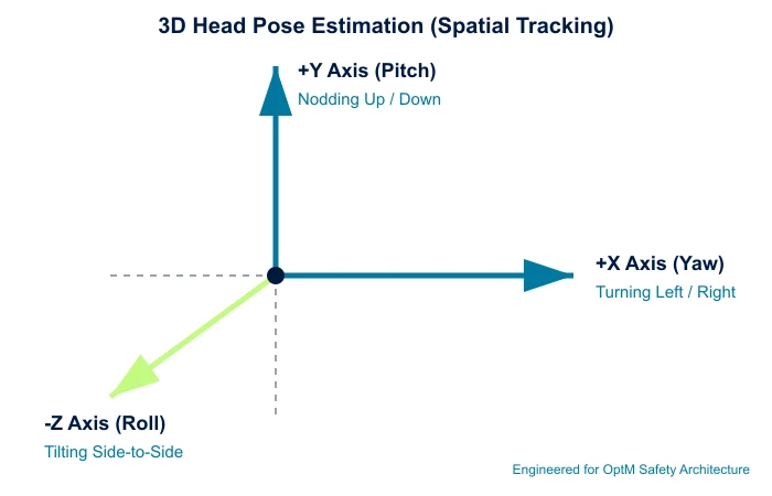
- Yaw (Horizontal Vector): Tracks horizontal head turns. If the Yaw angle deviates past +/- 20 degrees for an extended block, the system infers that the driver is scanning off-road environments or looking down at the center console.
- Pitch (Vertical Vector): Monitors vertical head slumping. A sharp drop in the negative Pitch vector combined with diminished muscle control indicates a drowsy operator losing physical consciousness.
- Roll (Lateral Vector): Measures lateral neck tilting, helping identify severe slouching or physical impairment.
3.1 Eyelid Tracking and Temporal PERCLOS Calculations
To detect fatigue before a collision occurs, the vision pipeline calculates the Eye Openness Index (EOI) by measuring the vertical distance between the upper and lower eyelid landmarks relative to a fully open baseline frame.
Eye Openness Index (EOI) = (Top Eyelid Landmark Y - Bottom Eyelid Landmark Y) / Baseline Height
The system uses this index to continuously compute PERCLOS (Percentage of Eye Closure), the standard metric for automotive fatigue tracking.
PERCLOS = (Total Frames where EOI is less than 20%) / (Total Frames in 60-Second Window)
If the cumulative PERCLOS score crosses a mathematically validated threshold (typically exceeding 15% over a moving 30-to-60-second window), the edge AI classifies the driver's state as severely fatigued. This precision prevents false alarms from normal, fast blinks (which last between 100 to 400 milliseconds) while capturing slow, voluntary eyelid droops that characterize micro-sleep events.
3.2 3D Gaze Vector Construction for Visual Distraction
A driver can keep their head facing straight forward while completely diverting their vision to an off-road distraction. To identify this behavior, the system calculates a 3D gaze vector.
[Pupil Center Coordinates] + [Corneal Reflection (IR Glint)] → [3D Gaze Vector Engine] → [Spatial Matrix Match]
The computer vision models track the relative offset between the geometric center of the pupil and the stationary infrared glint projected onto the cornea by the 940nm emitters. This spatial delta allows the software to output a directional vector in 3D space.
This vector is mapped directly against a localized coordinate matrix of the cabin interior, which includes the front windshield, side mirrors, and central infotainment cluster. If the gaze vector drifts away from the safe windshield zone for more than 2.0 consecutive seconds at highway velocities, a visual distraction alert is generated.
3.3 Facial Action Coding System (FACS) for Cognitive Staring
Cognitive distraction—or "highway hypnosis"—occurs when an operator looks at the road but their brain is disengaged from driving. To catch this state, the system tracks micro-expressions and changes in muscle groups via the Facial Action Coding System (FACS).
When a driver experiences a cognitive disconnect, their blink rate drops significantly, their gaze vector becomes rigidly fixed on a single forward coordinate, and their micro-saccades (tiny, rapid eye movements) stabilize. The edge AI runs a temporal recurrent neural network (such as a Long Short-Term Memory or LSTM block) over these metric vectors to isolate and flag cognitive impairment even when the eyes remain open.
4. The Response Architecture: Network Broadcasting and HMI
Detecting fatigue or distraction at the edge has zero safety value if the system cannot communicate those anomalies to the rest of the vehicle infrastructure in real time.
[DMS NPU Core] → [ASIL-B Safety Microcontroller] → [CAN-FD Bus Frame] → [Cockpit Controller / ADAS ECU]
Protocol-Level Routing Over CAN-FD
The moment a behavioral classifier flags a risk state, the application layer sends an interrupt request to an integrated safety microcontroller. This controller packages the risk profile into a low-latency CAN-FD (Controller Area Network Flexible Data-rate) or Automotive Ethernet frame.
| Frame Component | Operational Payloads | Network Destination | Interrupt Status |
|---|---|---|---|
| Binary Risk Warning | High-Priority Bus | Instrument Cluster | Immediate Alert |
| Gaze Coordinates | X, Y, Z Vector Matrix | ADAS Controller | Path Planning Adjust |
| Fatigue Metric | Real-Time PERCLOS % | Telematics Unit | Fleet Logging |
This protocol-level execution guarantees that high-priority safety commands bypass lower-level network traffic, preventing data packet collisions across the vehicle's internal communication architecture.
Tiered HMI Warning Escalation
The vehicle's Cockpit Domain Controller intercepts the CAN-FD safety frame and triggers a multi-stage warning sequence on the digital instrument cluster. To optimize the driver's response, the human-machine interface (HMI) deploys a structured, progressive feedback loop:
[Visual Cue: Dashboard Cluster] → [Audio Cue: Spatial DSP Chimes] → [Haptic Cue: Steering/Seat Vibration]
- Stage 1 (Visual): A soft warning icon or textual message renders on the center console or heads-up display to prompt a gaze correction.
- Stage 2 (Auditory): If the gaze vector does not return to the road within milliseconds, the system routes high-frequency auditory alerts through specific cabin speakers to draw the driver's attention back to the road.
- Stage 3 (Haptic): For persistent distraction or micro-sleep events, the system engages high-intensity steering wheel or seat track haptic motors, physically alerting the operator to regain vehicle control.
5. System Fusion: Connecting Internal and External Safety Networks
Modern driver safety requires a bidirectional data exchange between internal in-cabin sensing and external environmental tracking. A vehicle's external ADAS modules cannot achieve optimal timing parameters if they operate blindly without human context.
When evaluating the data handshake of DMS vs ADAS, the engineering advantages of sensor fusion are clear.
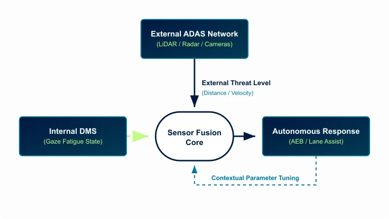
Sensor Fusion Workflows
Exterior camera arrays and forward radar systems excel at tracking external lane markers and surrounding traffic. However, they lack insight into driver preparedness. By unifying these nodes, the central domain controller can alter vehicle safety limits dynamically:
- If the external ADAS detects a slowing vehicle ahead, it evaluates the internal DMS network bus.
- If the internal metrics show the driver's 3D gaze vector is safely fixed on the hazard, the ADAS uses standard intervention timings.
- If the DMS reports that the driver is experiencing a micro-sleep or looking downward, the vehicle adjusts its safety parameters, lowering the Automatic Emergency Braking (AEB) engagement threshold to apply the brakes much earlier, mitigating or avoiding the collision entirely.
6. Embedded Hardware Engineering Challenges
Deploying a multi-layered neural network inside an automotive production platform introduces strict physical and computational constraints. Lab-tested models frequently crash or throttle when exposed to real-world automotive environments.
Managing Thermal and Computational Budgets
Running continuous, high-definition computer vision pipelines at 60Hz forces edge processors to execute billions of operations per second, generating significant computational heat.
[Raw 60Hz Stream] → [Hardware Accelerator (NPU)] → Low-Level INT8 Quantization → Reduced Thermal Footprint
Because camera enclosures are typically small and lack active cooling fans (to save space and weight behind the steering column or rearview mirror), software teams must optimize execution layouts. Engineers tackle these challenges by using advanced INT8 quantization, which converts heavy 32-bit floating-point neural networks into high-efficiency 8-bit integer formats. This reduction minimizes memory bandwidth demands and allows the code to run within the strict thermal limits of the local ECU.
Edge-Case Robustness and Validation Matrices
To secure factory-level safety certifications, the underlying computer vision models must maintain deterministic accuracy across thousands of unexpected real-world edge cases.
| Environmental/Physical Obstacle | Engineering Mitigation Strategy |
|---|---|
| Polarized / High-Tint Sunglasses | Pulsed 940nm Active NIR Illumination |
| Particulate Matter / Heavy Dust | Bandpass Optical Filter Over Image Lens |
| Physical Occlusion (Masks/Beards) | Dynamic Geometric Part-Based Landmark Mesh |
| Rapid Exterior Light Transitions | Microsecond Auto-Exposure Tracking Loops |
Developing these resilient, production-ready vision loops requires executing extensive testing and validation across a wide spectrum of road lighting conditions, facial characteristics, and cabin vibrations to prevent false alerts or catastrophic tracking dropouts.
Frequently Asked Questions
Can a DMS distinguish between checking side mirrors and actual distraction?
Yes. The 3D gaze vector engine calculates the precise angular orientation of the driver's line of sight relative to the cabin's spatial geometry. Side mirrors are mapped out as valid driving coordinates within the system's tracking matrix. If the driver's gaze vector transitions to a mirror for an acceptable duration (typically under 1.5 seconds), the software classifies it as active hazard scanning rather than a distraction anomaly.
How does the system handle face tracking if a driver is wearing an N95 medical mask or has thick facial hair?
When lower facial features like the mouth or jawline are obscured, standard global landmark models fail. Advanced architectures mitigate this by using part-based neural network models. If the system detects an occlusion over the lower face, it dynamically weights its tracking logic to rely exclusively on upper facial features—focusing on eye contours, eyebrow vectors, and the upper bridge of the nose to maintain an uninterrupted lock on head pose and fatigue states.
What happens to the system's compute performance if an image sensor gets partially blocked by dust?
Production-grade systems feature integrated Built-In Self-Test (BIST) routines and diagnostic fault logic. If dust, dirt, or manual blocking prevents the facial landmark tracking loop from operating effectively, the system does not fail silently. It instantly generates an active diagnostic trouble code (DTC) and broadcasts it across the vehicle network to notify the cluster that safety monitoring features are temporarily offline.
Why is an integrated RTOS mandatory over a standard Linux operating system for vision processing?
General-purpose operating systems utilize non-deterministic task scheduling, meaning critical code execution can be delayed if the processor prioritizes background data updates or media functions. A Real-Time Operating System (RTOS) operates on strict, deterministic priority-based scheduling. This guarantees that safety-critical computer vision and network broadcasting tasks are allocated fixed processing budgets, executing with sub-millisecond reliability under every operational state.
Optimizing Your Automotive Engineering Lifecycle
Architecting a safe, autonomous-ready cabin requires deep expertise in low-level firmware development, high-frequency deep learning optimization, and precise vehicle network integration. Navigating the balance between high-bandwidth vision pipelines, strict hardware processing budgets, and rigid functional safety compliance is a complex engineering task.
Explore how OptM can support your platform development goals. Our embedded engineering and product engineering teams work closely with global OEMs and Tier 1 suppliers to design, validate, and scale robust, production-ready safety architectures. Review our production-ready Driver Monitoring System solutions today to elevate your intelligent cabin architecture.