
Content Writer & SEO Specialist
Content Writer & SEO Specialist
Aditya Sharma is a content writer at OptM Solutions specializing in automotive electronics, embedded systems, telematics, electric vehicle technologies, connected mobility, and autonomous driving technologies.
LinkedIn ProfileModern vehicles rely on much more than mechanical braking components to ensure safety. Behind every Anti-lock Braking System (ABS) is a carefully designed architecture that continuously monitors wheel behavior, processes sensor data, and adjusts braking force in real time.
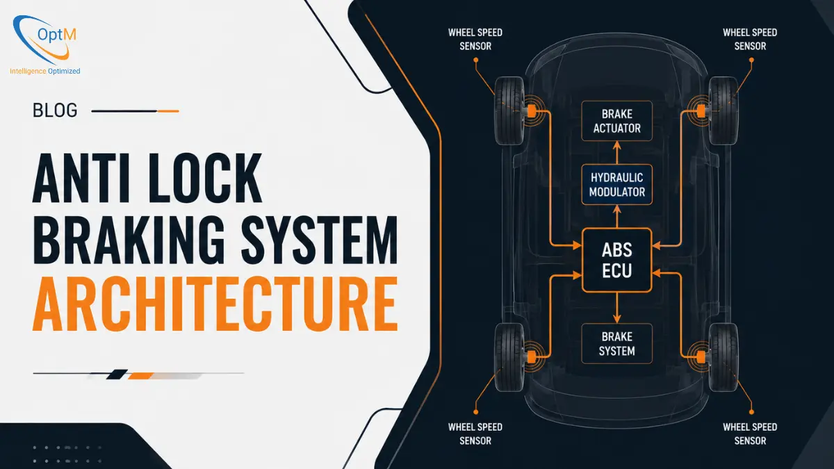
Anti Lock Braking System Architecture refers to the complete framework of sensors, electronic control units, hydraulic components, and communication networks that work together to prevent wheel lock-up during braking. Understanding this architecture helps explain how ABS improves vehicle stability, steering control, and overall road safety.
If you're new to the technology, our guide on What is Anti Lock Braking System provides a useful foundation before exploring its architecture in detail.
What Is Anti Lock Braking System Architecture?
Anti Lock Braking System Architecture is the structural and functional design that enables ABS to detect wheel slip and regulate braking pressure automatically. Rather than relying on a single component, ABS operates through multiple interconnected systems that exchange data and make decisions within milliseconds.
In modern vehicles, the ABS architecture serves as a critical part of the broader vehicle safety ecosystem. It not only prevents wheel lock-up but also supports advanced technologies such as Electronic Stability Control (ESC) and Traction Control Systems (TCS).
The effectiveness of an ABS depends largely on how efficiently its components communicate and respond during sudden braking situations.
Core Components of an Anti Lock Braking System Architecture
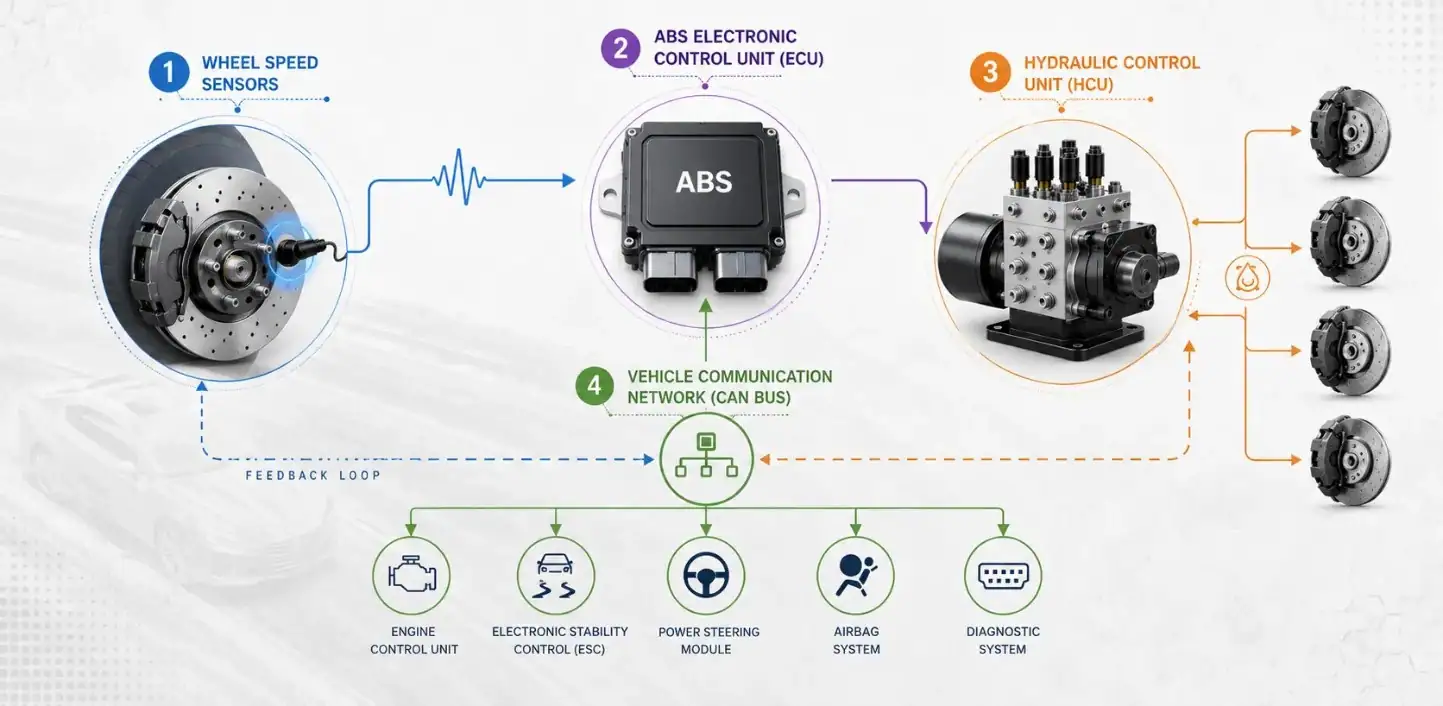
A typical ABS architecture consists of four primary Components or elements that work together to deliver controlled and stable braking performance.
Wheel Speed Sensors
Wheel speed sensors continuously monitor the rotational speed of each wheel and send this information to the ABS Electronic Control Unit.
When one or more wheels begin slowing down significantly faster than the others, the sensors help identify a potential wheel lock-up condition. This real-time monitoring forms the foundation of ABS operation.
ABS Electronic Control Unit (ECU)
The ABS ECU acts as the brain of the system.
It receives wheel speed data, analyzes wheel slip conditions, and determines whether braking intervention is required. Modern automotive-grade ECUs use embedded control algorithms that can process sensor inputs and make braking decisions within milliseconds.
In safety-critical automotive environments, the ECU must deliver consistent and reliable performance under varying road and vehicle conditions.
Hydraulic Control Unit (HCU)
The Hydraulic Control Unit is responsible for physically adjusting brake pressure based on instructions received from the ECU.
When wheel lock-up is detected, the HCU can:
- Reduce brake pressure
- Maintain brake pressure
- Increase brake pressure
This rapid modulation allows the wheels to continue rotating while maintaining sufficient braking force.
Vehicle Communication Network
Modern ABS systems do not operate in isolation. They communicate with other vehicle electronics through communication protocols such as CAN (Controller Area Network).
This connectivity allows the ABS to share information with multiple vehicle systems and contribute to overall vehicle stability and safety functions.
How Anti Lock Braking System Architecture Works
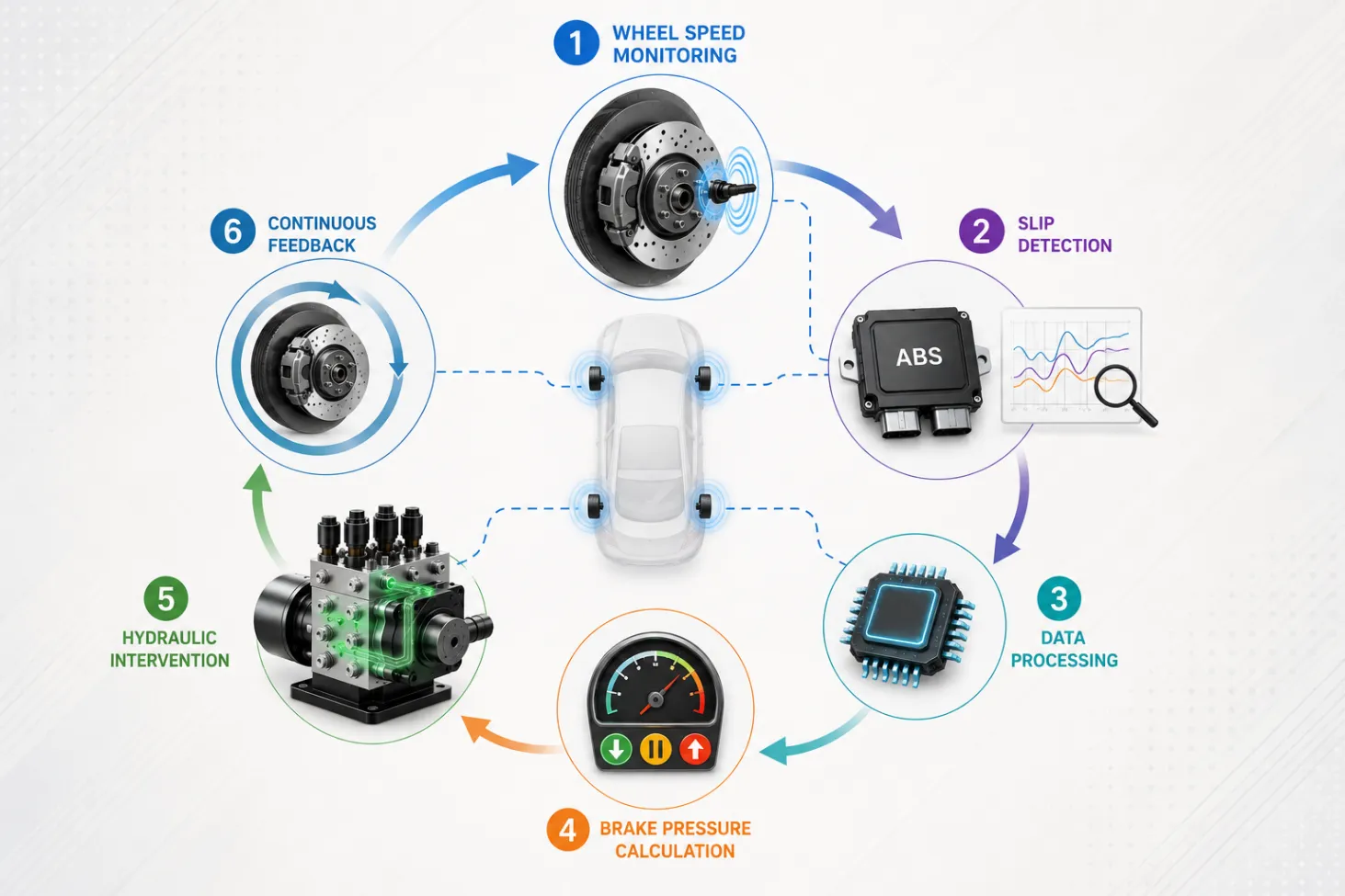
The Anti Lock Braking System Architecture operates through a continuous feedback loop that monitors wheel behavior and adjusts braking force whenever necessary.
The process typically follows these steps:
1. Wheel Speed Monitoring
Wheel speed sensors continuously measure the rotational speed of each wheel during vehicle operation.
2. Slip Detection
The ABS ECU compares wheel speed values and identifies abnormal deceleration patterns that may indicate wheel lock-up.
3. Data Processing
Using embedded control algorithms, the ECU calculates wheel slip ratios and determines whether corrective action is required.
4. Brake Pressure Calculation
The ECU decides whether brake pressure should be reduced, maintained, or increased.
5. Hydraulic Intervention
The Hydraulic Control Unit executes the ECU's instructions by adjusting brake pressure accordingly.
6. Continuous Feedback
The sensors continue monitoring wheel behavior, allowing the system to repeat this process multiple times per second until stable braking conditions are restored.
This closed-loop architecture enables drivers to maintain steering control during emergency braking situations. According to the National Highway Traffic Safety Administration , ABS helps drivers maintain steering capability while braking hard, reducing the risk of losing vehicle control. Reference:
For a deeper explanation of the braking sequence, you can also explore How Anti Lock Braking System Works.
Integration of ABS Architecture with Modern Vehicle Systems
As vehicle safety technologies continue to evolve, ABS architecture has become a foundational component for several advanced systems.
Today, ABS frequently integrates with:
- Electronic Stability Control (ESC)
- Traction Control Systems (TCS)
- Powertrain Control Modules
- Advanced Driver Assistance Systems (ADAS)
- Vehicle Diagnostics Systems
For example, ESC relies on ABS sensors and hydraulic control capabilities to selectively apply braking force to individual wheels when vehicle instability is detected.
Similarly, traction control systems use ABS sensor data to identify wheel spin and improve vehicle traction on slippery surfaces.
This integration highlights how modern ABS architectures contribute far beyond basic braking functionality.
Challenges in Anti Lock Braking System Architecture Design
Designing an effective ABS architecture involves several engineering challenges.
Real-Time Processing Requirements
Braking decisions must be made within milliseconds, leaving little room for processing delays.
Sensor Accuracy and Reliability
The performance of the entire system depends on accurate wheel speed measurements under different road and environmental conditions.
Functional Safety Requirements
ABS architectures must comply with stringent automotive safety standards to ensure reliable operation throughout the vehicle lifecycle.
Growing Software Complexity
As modern vehicles become increasingly software-defined , ABS systems must support more sophisticated control strategies while maintaining predictable performance.
Balancing safety, reliability, cost, and system complexity remains a key challenge for automotive engineering teams.
Conclusion
Anti Lock Braking System Architecture is the foundation that enables modern ABS technology to function effectively. By combining wheel speed sensors, electronic control units, hydraulic modulation systems, and vehicle communication networks, the architecture helps prevent wheel lock-up and maintain vehicle stability during braking.
As automotive safety systems become more interconnected, ABS architecture continues to play a central role in supporting technologies such as ESC, traction control, and advanced driver assistance systems.
For automotive manufacturers, OEMs, and mobility solution providers, understanding this architecture is essential when developing safer and more intelligent vehicle platforms. Explore OptM's ABS Module and automotive embedded engineering capabilities to understand how modern braking systems can be designed for reliability, performance, and seamless vehicle integration.